1-28
Installation 15088:J 10/22/99
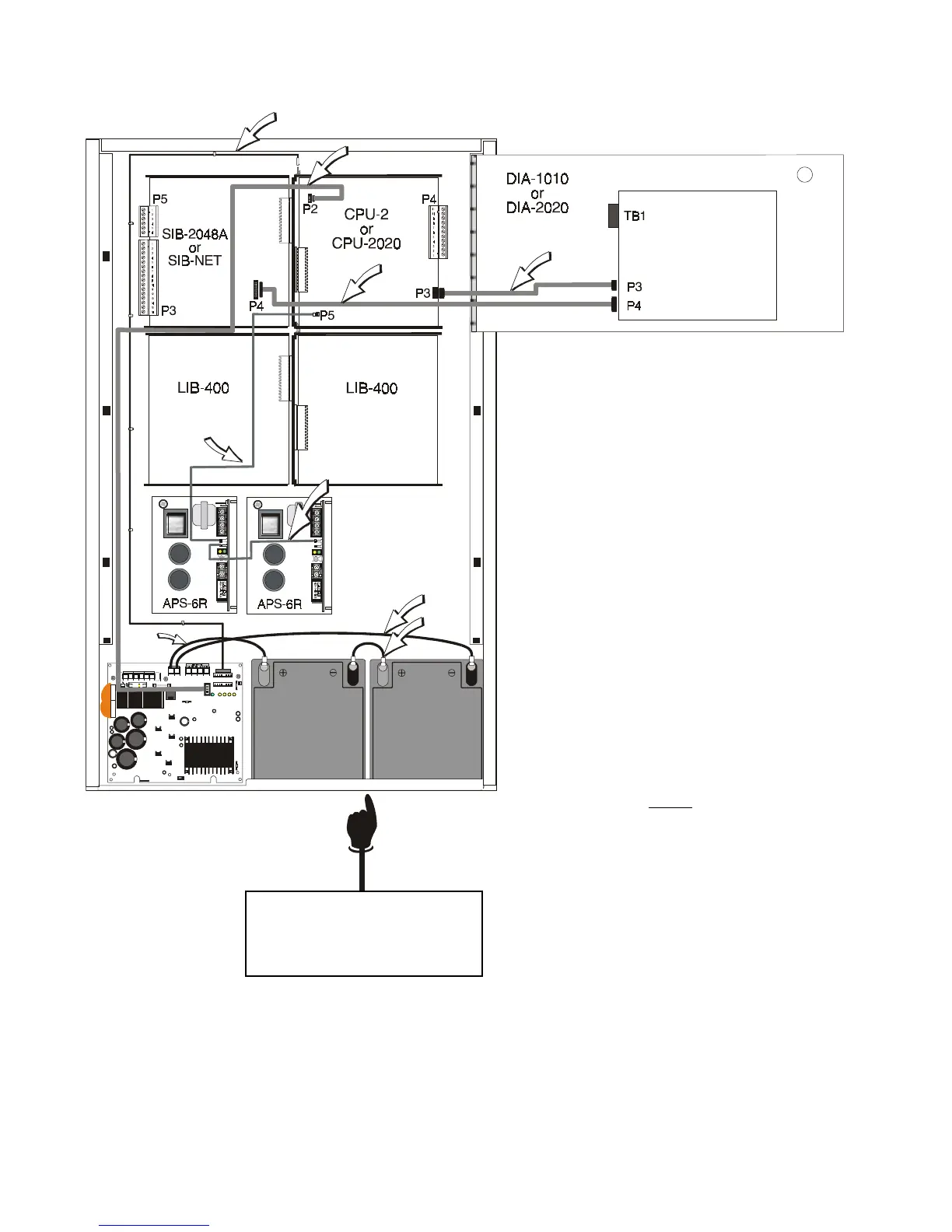
Figure 2.7-2 Wiring Placement Diagram
NOTE
The battery charger output is not power-
limited. All wiring connected to these ter-
minals must remain at least ¼ inch (6.35
mm) from all power-limited wiring. Refer
to Figure 2.7-3 for wiring information.
Figure 2.7-2 depicts typical system cable placement.
CAUTION!
Be sure to allow for BP-3 Battery
Dress Panel screw clearance
between batteries here.
71030 (to ICA)
71031
71046
75226
71033
71033
71072
71070
www.PDF-Zoo.com
 Loading...


