1-56
Installation 15088:J 10/22/99
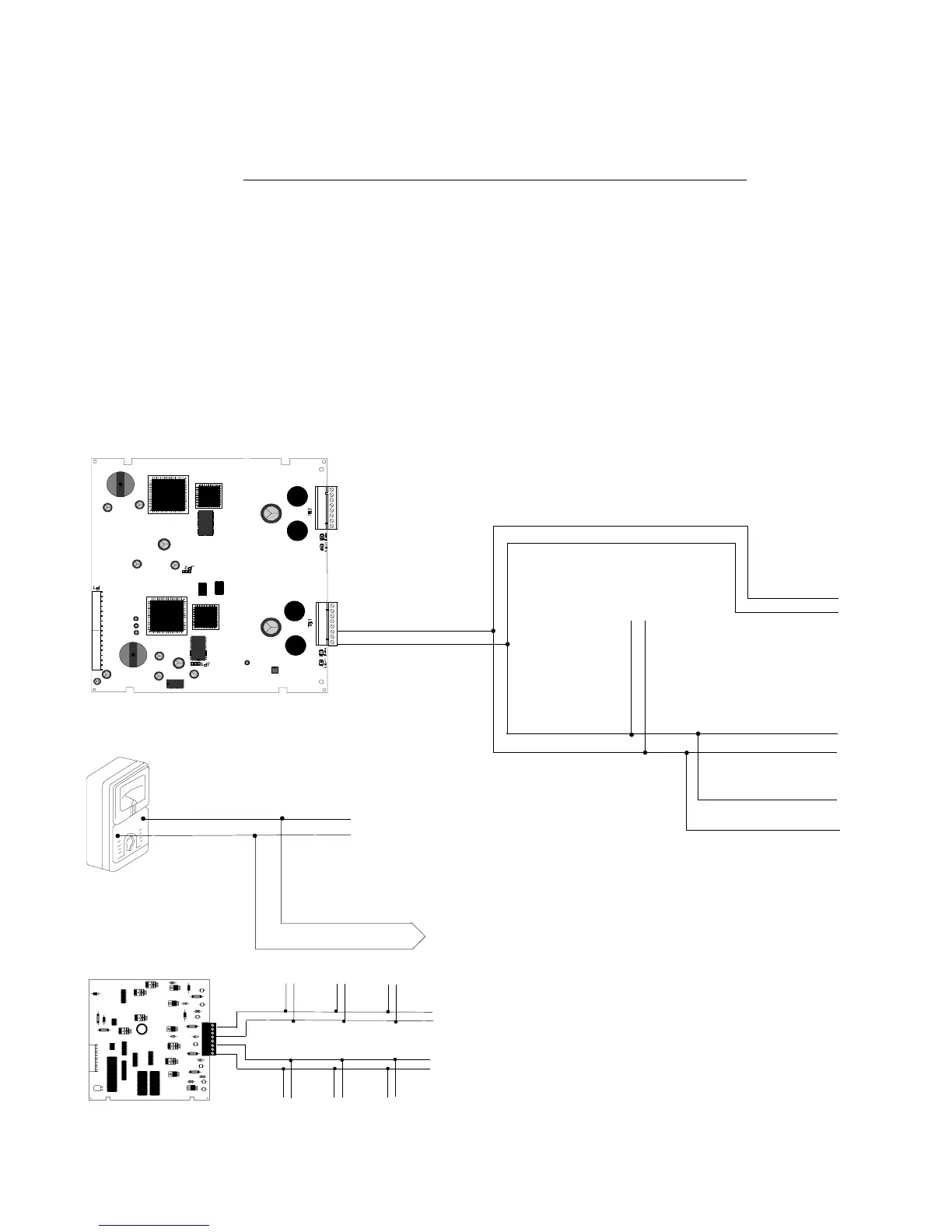
Figure 4.3-1 SLC Loop Wiring Requirements (Style 4)
Section 4.3 LIB SLC Loop Wiring Requirements
Branch Resistance
With the SLC disconnected from the LIB terminals, short the termination point of one branch at a time and mea-
sure the DC resistance from the beginning of the channel to the end of that particular branch. The total DC
resistance from the LIB-200 panel to branch end cannot exceed 40 ohms. The total DC resistance from the LIB-
200A panel or the LIB-400 panel to branch end cannot exceed 50 ohms. Repeat this procedure for all remaining
branches. Refer to Figure 4.3-1 for Style 4 and Figure 4.3-2 for Style 6.
For each channel
Add the lengths of all the branches on one SLC Loop Channel. On the LIB-200, this sum cannot exceed 10,000
feet (3048 meters)per channel. On the LIB-200A or the LIB-400, this sum cannot exceed 12,500 feet (3810
meters) per channel.
LIB-200:
(Branch A) + (Branch B) + (Branch C) + (Branch D) + (Branch E) = 10,000 feet (3048 meters) or less
LIB-200A or LIB-400:
(Branch A) + (Branch B) + (Branch C) + (Branch D) + (Branch E) = 12,500 feet (3810 meters) or less
Branch A
SLC Loop
Channel A
Branch D
Branch E
Branch C
Branch B
LIB
Branch
Channel A or B
THE TOTAL OF ALL BRANCHES ON CHANNEL A:
LIB-200 must be less than or equal to 10,000 feet (3048 meters)
LIB-200A /LIB-400 must be less than or equal to 12,500 feet (3810
meters)
THE TOTAL OF ALL BRANCHES ON CHANNEL B:
LIB-200 must be less than or equal to 10,000 feet (3048 meters)
LIB-200A /LIB-400 must be less than or equal to 12,500 feet
(3810 meters)
LIB-400
NOTE: SLC Resistance Measurement
When power is removed from the SLC, the positive
side of the circuit is opened at each ISO-X isolation module or
isolator detector base. To measure the SLC circuit resistance,
temporarily place a jumper between Terminals 2 and 4 on each
ISO-X while taking measurements. Remember to remove all the
jumpers and test all isolator modules when you have
finished taking the readings.
www.PDF-Zoo.com
 Loading...


