1-54
Installation 15088:J 10/22/99
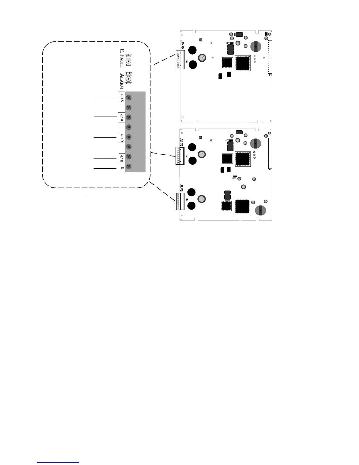
Figure 4.2-2 Loop Interface Boards
LIB-200A
LIB-400
NOTES:
• Only one earth ground connection is required on
the LIB-400 at either TB1 or TB2.
• Silkscreen markings on TB2 of the LIB400 vary from
the above illustration: twos instead of ones are used,
so the markings are +L2A, -L2A, +L2B, and -L2B.
Surge Suppression
There are three (3) primary surge protectors that are approved for use with this FACP.
• DTK-2LVLP-F Diversified Technology Group, Inc. 1720 Starkey Rd. Largo, FL 33771 (727) 812-5000
• SLCP-030 EDCO 1805 N.E. 19th Ave. Ocala, FL 34470 (352) 732-3029
• PLP-42N Northern Technologies, Inc. 23123 E. Madison Ave. Liberty Lake, WA 99019 (800) 727-9119
Note: For detailed information refer to the installation documentation that was supplied with the unit.
One primary surge protector must be used with each SLC wiring pair whenever SLC wiring runs outside the building.
• Install primary protection only as shown in this document.
• Refer to NEC Article 800 and local building code requirements.
Additional primary surge suppressors maybe added as required by the NEC. Add these additional
suppressors in series with the SLC wiring at the building entry/exit.
Wiring connected to the surge suppressor output must remain within the building while wiring connected to
the surge suppressor input may be routed outside the building as shown in “Building Entry/Exit Connections”
in Figure 4.2-3.
Suppressor Installation
Mounting is inside the FACP enclosure or in a separate enclosure listed for fire protective signalling use.
Locate on an available stud and secure with nut.
Unit is connected in series with the SLC Loop to protect the control panel.
Provide a common ground to eliminate the possibility of a differential in ground potentials.
SLC Port A+
SLC Port A-
SLC Port B+
SLC Port B-
Connect to Earth
Ground using
supplied cable
www.PDF-Zoo.com
 Loading...


