1-29
Installation 15088: J 10/22/99
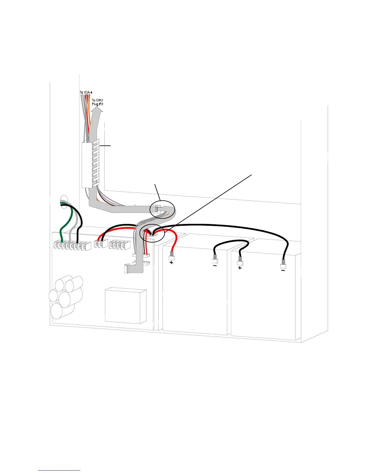
Figure 2.7-3 depicts a typical AM2020/AFP1010 installation and is provided as a guide for proper wiring
placement. The AC and battery wiring are not power-limited. A separation of at least ¼ inch (6.35 mm) must be
maintained between power-limited and nonpower-limited wiring. Install the tie wraps and adhesive squares as
indicated in Figure 2.7-3.
Figure 2.7-3 Power-Limited and Non Power-Limited Wiring
Adhesive square and tie-wrap on
top of power supply chassis
affixing
nonpower-limited
wiring.
Adhesive square and tie-wrap on back of
cabinet affixing
power-limited
wiring.
Figure 2.7-4 is provided as a guide for dress panel placement.
Wire Channel (Model WC-2)
www.PDF-Zoo.com
 Loading...


