1-65
Installation 15088: J 10/22/99
Section 4.6 Monitor Modules
The MMX-101 Monitor Module (Figure 4.6-2)
The MMX-101 Monitor Module is an addressable module that is functionally and electrically identical to an MMX-1
Monitor Module (configured for NFPA Style B), but offered in a smaller package for mounting directly in the
electrical box of the contact-type device being monitored. Unlike the MMX-1, the MMX-101 does not have an
LED indicating polling or alarm condition.
The MMX-1, MMX-2 and MMX-101 Monitor Modules are addressable modules that monitor normally open contact,
shorting type and alarm initiating devices. The MMX-2 can also monitor conventional two-wire smoke detectors. The
MMX-1 and MMX-2 Initiating Device Circuits (IDC) can be wired as an NFPA Style B or Style D Initiating Device
Circuits; the MMX-101 Initiating Device Circuits (IDC) can be wired Style B only. There is no limit to the number of
contact-type devices installed on a monitor module circuit (See NFPA 72 for possible code imposed limits. See the
Device Compatibility document for the maximum number of 2-wire smoke detectors that can be connected to the
MMX-2.) Refer to Figures 4.6-3 and 4.6-4 for MMX-1/MMX-2 wiring diagrams.
The MMX-1 and MMX-2 Monitor Modules (Figure 4.6-1)
SLC Loop Connections
Connect the SLC Loop to MMX-1 or MMX-2 terminals 1(-) and 2 (+). The MMX occupies one module address on
the SLC Loop. Set the rotary switches on the MMX to the particular SLC address required (each MMX requires
a unique module address, 01-99).
NFPA Style B Initiating Device Circuit
Connect the alarm initiating devices to a single two-wire circuit. This circuit cannot be T-Tapped or branched in
any fashion, and must be terminated across the last device by a listed ELR. Connect the circuit to MMX-1/MMX-
2 terminals 6 (-) and 7 (+).
NFPA Style D Initiating Device Circuit
Connect the normally open contacts of the alarm initiating devices as shown in Figure 4.6-4. This circuit cannot
be T-Tapped or branched in any fashion. No external ELR is required for Style D wiring.
MMX-2 Operating Power
The MMX-2 requires connection of a Notifier 24V DC filtered and resettable power supply on Terminals 3(-) and
4(+). This power connection is supervised by the MMX-2. A maximum of 40 MMX-2 modules may be installed on
a LIB due to increased power consumption over the MMX-1. Only use 2-wire smoke detectors which are UL
compatibility listed. See the Notifier Device Compatibility Document 15378 for a listing of devices.
SLC Loop (-)
SLC Loop (+)
24V DC (-)
MMX-2 only
24V DC (+)
MMX-2 only
Style D (-)
Style D (+)
Style B (+)
Style B (-)
Figure 4.6-1 MMX-1 or MMX-2 Monitor Modules
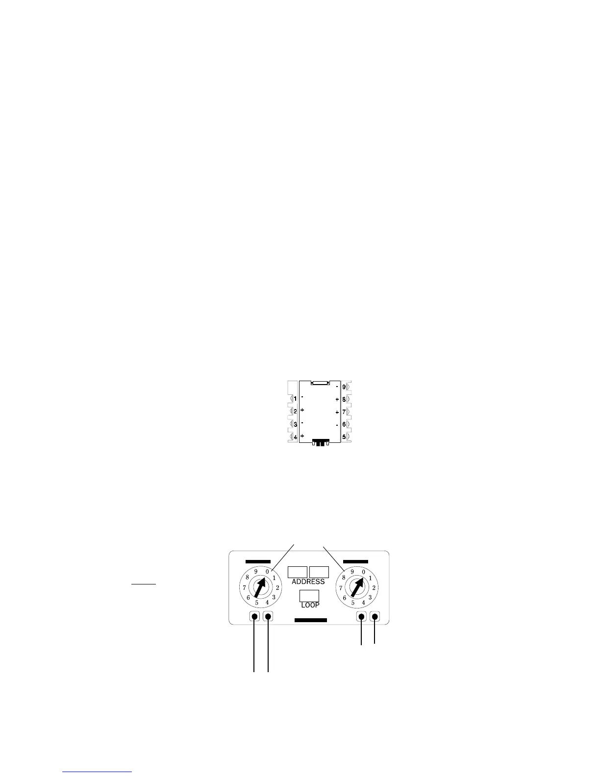
Set the module address with these switches
IDC (-) IDC (+)
(Yellow) (Violet)
NFPA Style B Initiating Device Circuit
Terminate with an End-of-Line Resistor 47K, 1/2-watt (A2143-00)
SLC Loop (+) (-) SLC Loop
(Red) (Black)
NOTE
For additional ratings,
refer to Appendix A.
Figure 4.6-2 MMX-101 Monitor Module
www.PDF-Zoo.com
 Loading...


