Chapter 5 IEEE 1284 Parallel Interface
300
Host Logic High—Driven by the host. When set to high, the host
indicates all of its signals are in a valid state. When set to low, the host
indicates its power is off or its signals are in an invalid state.
nInit —Resets init interface from the host.
Terminating Resistor Configurations
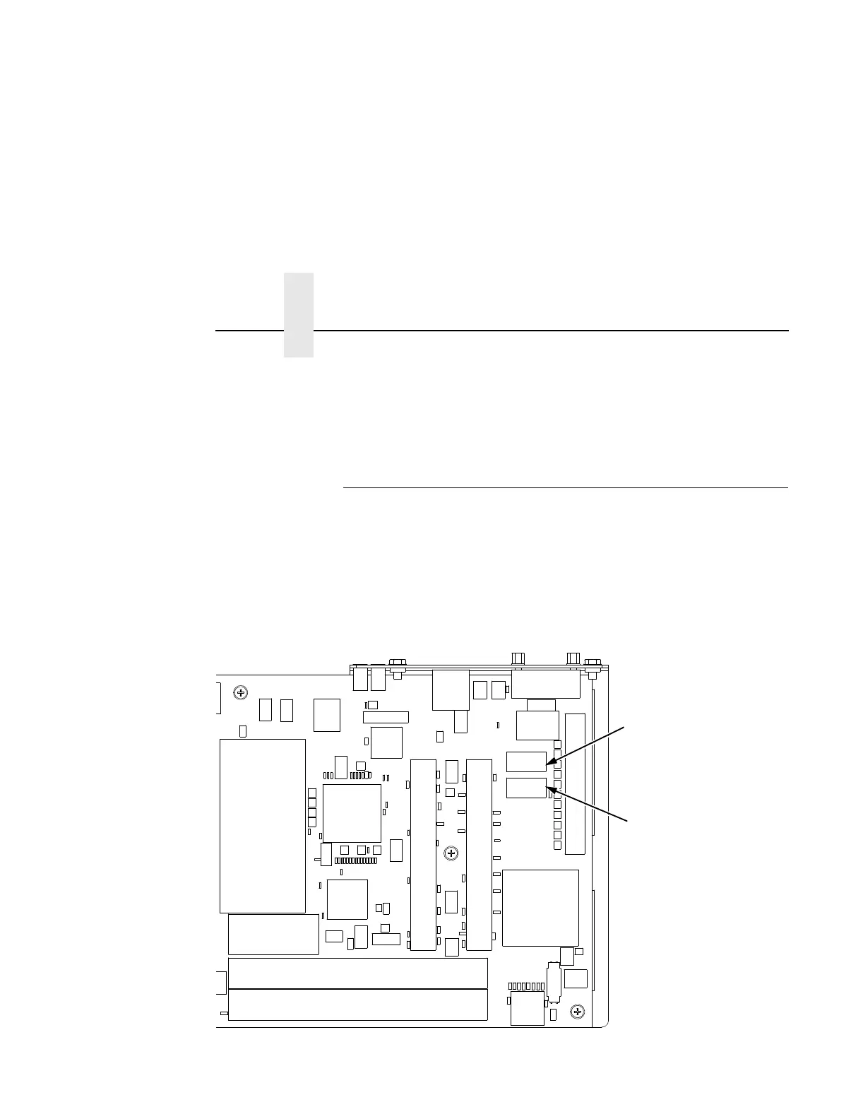
The factory equips the printer with several resistors that are used for
parallel interface configurations and are suitable for most applications.
These 470 ohm pull-up and 1K ohm pull-down terminating resistors are
located at RP1 and RP2, shown in Figure 24.
If the values of these terminating resistors are not compatible with the
particular interface driver requirements of your host computer, you may
need to install resistors with different pull-up and pull-down values.
Figure 24. Resistor Locations
Default: 470 Ohm
Alt 1: 220 Ohm
Alt 2: 1K Ohm
Default: 1K Ohm
Alt 1: 330 Ohm
Alt 2: None
RP1
RP2
 Loading...