WARNING
Do not use the status of the indicators on the NX-series Safety Control
Units for safety operations.
This will compromise the safety functions of the Unit and may cause
serious injury in the event of an accident.
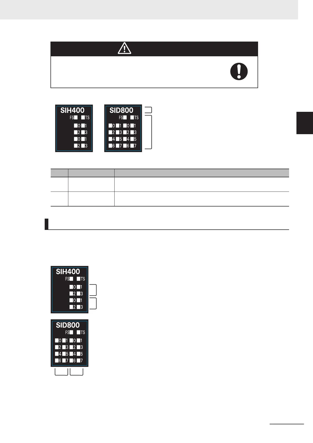
The indicator pattern depends on the number of input points, as shown below.
Unit with 4 I/O Points Unit with 8 I/O Points
(A)
(B)
Letter Name Function
(A) Model number dis-
play
Displays part of the model number of the Safety I/O Units.
The model number indication is red on all Safety Control Units.
(B) Indicators Show the current operating status and communications status of the Safety I/O
Units.
Safety Input Unit Operation Status Indicators
Indicators to show the operation status of the Safety Input Unit are located in the center of the front
side of the Safety Input Unit.
The following section describes the specifications of each indicator.
l
TS Indicator
The TS indicator shows the current status of the Safety Input Unit and its communications status
with the NX Bus Master.
2 Specifications
2 - 25
NX-series Safety Control Unit User's Manual (Z930)
2-2 Safety Input Unit
2
2-2-3 Indicators

 Loading...


