9-8
GENERATOR TESTING
This section covers test procedures for the rotor
and stator windings. Begin with the
Field Voltage
Test,
following, to help locate possible problems.
Check all wire harness connectors and leads for
continuity prior to generator testing. Refer to Sec-
tion
12. Wiring Schematic/Diagram.
Field Voltage Test
Perform the Field Voltage Test if low or no generator
output voltage is produced to confirm that field volt-
age is available to the rotor brushes through the
voltage regulator for field flashing and voltage build-
up.
WARNING
Electrical shock can cause severe
personal injury or death. Use extreme caution
when working on electrical circuitry. Attach and
remove meter leads only when genset is not op-
erating. Do Not touch meter or meter leads dur-
ing tests.
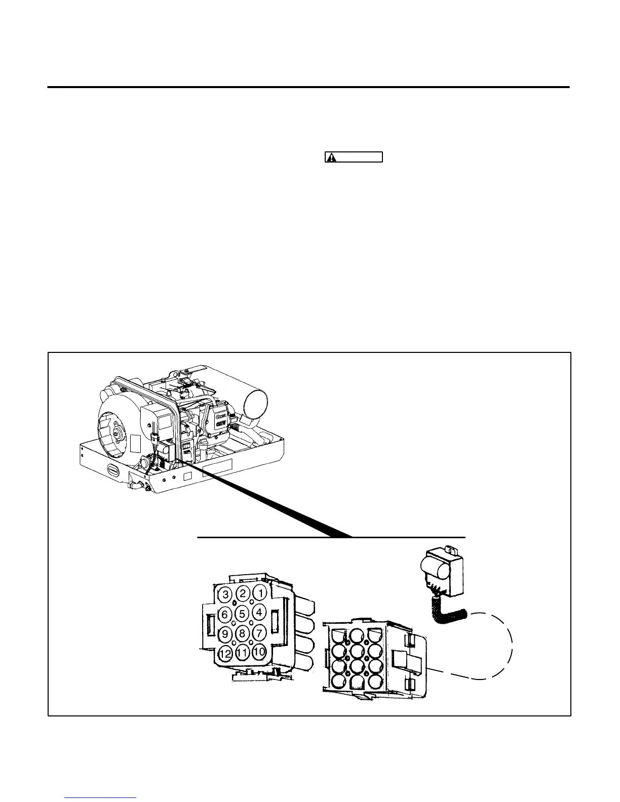
The voltage regulator plug J4 remains connected to
wire harness plug P4 for Test A and B. The voltme-
ter leads should be secured so that they are not be-
ing held during testing. (Use long pointed test leads
or paper clips connected with alligator clips to the
test leads.) Refer to Figure 9-6.
ES2018s
VOLTAGE
REGULATOR VR1
J4 CONNECTOR
P4 CONNECTOR
SPEC A MODEL SHOWN
FOR REFERENCE -
SEE FIGURE 62 FOR
BEGIN SPEC B MODELS
FIGURE 9-6. VOLTAGE REGULATOR CONNECTOR PLUG (P1)
 Loading...

