10-15
Piston Ring Thickness:
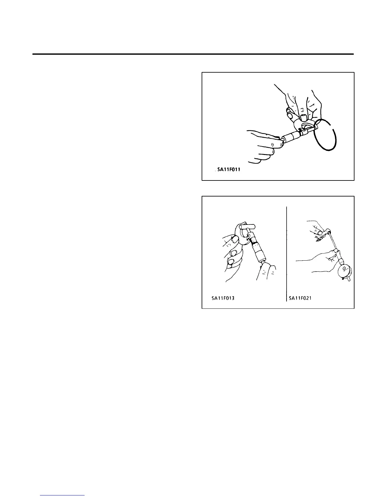
1. Measure the piston ring thickness with an out-
side micrometer (see Figure 10-28).
2. If the thickness is less than the allowable limit,
replace the ring.
Piston Assembly
Install the rings on the piston beginning with the oil
control ring. Use a piston ring spreader to prevent
twisting or excessive expansion of the ring. Com-
pression rings are marked with the word top or a
mark on one side of the ring to indicate which side
faces the top of the piston. Oil ring rails may be
installed either way. Stagger ring gaps 120 degrees
apart. Do not position ring gaps on thrust face of cyl-
inder.
Clearance between Piston Pin and
Connecting Rod Small End Bore
1. Measure the piston pin O.D. and connecting
rod small end bore with a micrometer (Figure
10-29). Then calculate the difference.
2. If the clearance exceeds the allowable limits,
replace them.
FIGURE 10-28. RING THICKNESS
FIGURE 10-29. PISTON PIN AND CONNECTING
ROD CLEARANCE
 Loading...

