8-14
Carburetor Mixture Screw Adjustments
(Does Not Apply to Spec D and Later)
The most common causes of poor carburetion are
the idle and main mixture screws being out of ad-
justment and contamination in the carburetor. Vari-
ation from the correct mixture settings can cause
serious engine problems. Too rich a mixture wastes
fuel and increases engine wear by washing the lu-
bricant from the cylinder walls and diluting the
crankcase oil. Too lean a mixture causes power
loss, flat spots in acceleration, and a tendency to
burn valves and spark plugs.
Unless a carburetion problem is indicated, the mix-
ture screw settings should not be changed. This
does not include problems due to high altitude,
which can usually be corrected with a small adjust-
ment of the main mixture screw within the range
provided by the limiter cap. The limiter cap on the
main mixture screw should not be removed unless
the carburetor has been overhauled or is way out of
adjustment. Before making adjustments, make
sure the ignition system is working properly.
CAUTION
Forcing the mixture adjustment
screws tight will damage the needle and seat.
Turn in ONLY until light resistance can be felt.
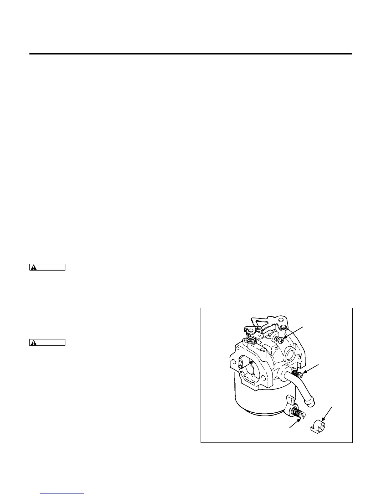
To make preliminary mixture screw settings:
Remove the limiter cap from the main adjustment
screw. Turn both of the mixture screws in until lightly
seated (Figure 8-11), then turn the main screw out 2
turns and the idle screw out 2-1/2 turns.
CAUTION
A hot genset can cause severe
burns. Always allow the genset to cool before
touching any components or removing any
parts.
Start the engine and allow it to run for ten minutes.
Use the following procedure to adjust the mixture
screws:
1. Stop the genset and connect a voltmeter, fre-
quency meter and load bank to the generator
output leads.
2. Start the genset and apply the rated load. Verify
that the frequency is within 60.5 1 Hz. Adjust
the governor speed adjustment screw if neces-
sary to obtain the required frequency.
3. Turn the main adjustment screw inward until
voltage or frequency drop and then outward
until voltage or frequency drop again. Locate
the point where voltage and frequency are the
highest. From this point turn the main adjust-
ment screw out an additional 1/4 turn. Install
the limiter cap so it is vertical.
4. Remove the load and verify that the frequency
is within 62.5 0.5 Hz on 60 Hz models or 52
0.5 Hz on 50 Hz models. Adjust the governor
speed adjustment screw if necessary to obtain
required frequency.
5. Turn the idle adjust screw inward until voltage
and frequency drop and the engine begins to
run rough or hunt. Back the idle screw out until
the engine runs smooth without hunting.
6. Pull the governor linkage toward the front of the
genset so that the throttle lever on the carbure-
tor is resting against the throttle stop screw
(Figure 8-11). Adjust the stop screw to obtain a
setting of 55 1 Hz (45 1 Hz on 50 Hz units).
7. Readjust the governor speed screw to within
62.5 0.5 Hz on 60 Hz models or 52 0.5 Hz
on 50 Hz models at no-load. Observe the sen-
sitivity of the genset. If necessary, adjust the
governor sensitivity as specified in
Governor
on Page 8-9.
FS1807-2s
LIMITER
CAP
MAIN
ADJUSTMENT
SCREW
IDLE
ADJUSTMENT
SCREW
THROTTLE
STOP SCREW
FIGURE 8-11. MIXTURE SCREW ADJUSTMENT
(PRIOR TO SPEC D)
 Loading...

