8-10
ence between no-load and full-load) without
causing a hunting condition. To increase the
sensitivity, turn the adjustment screw counter-
clockwise. To decrease the sensitivity, turn the
adjustment screw clockwise.
6. Recheck the speed setting made in step 3 and
readjust if necessary.
7. Set the carburetor throttle stop screw as speci-
fied in the Fuel System section.
If the governor action is erratic after adjustments
are made, loosen the governor arm mounting bolt
and rotate the shaft fully clockwise, then retighten
the bolt. Reset the governor adjustments and re-
check speed and droop. Springs tend to lose their
calibrated tension through fatigue after long usage.
It may be necessary to put the stationary end of the
spring in a different hole to change the tension, or
replace the spring altogether. If this does not im-
prove operation, the problem may be within the gov-
ernor mechanism (see Section
10.
Engine Block
Assembly
).
TABLE 8-1 CHECKING VOLTAGE AND
SPEED/FREQUENCY
60 Hz 50 Hz 50 Hz
1∅, 2Wire 1∅, 2Wire 1∅, 2Wire
120 V 220 V 240 V
Voltage
Maximum NoLoad 126 235 256
(Typical NoLoad) (125) (228) (248)
Minimum Full Load 108 205 224
(Typical FullLoad) (118) (215) (236)
Speed/Frequency
Maximum NoLoad
Speed (rpm) 3780 3150 3150
Frequency (Hz) 63 52.5 52.5
(Typical Frequency) (62.5) (52) (52)
Minimum FullLoad
Speed (rpm) 3570 2940 2940
Frequency (Hz) 59.5 49 49
(Typical Frequency) (59.5 (49.5 (49.5
60.5) 50.5) 50.5)
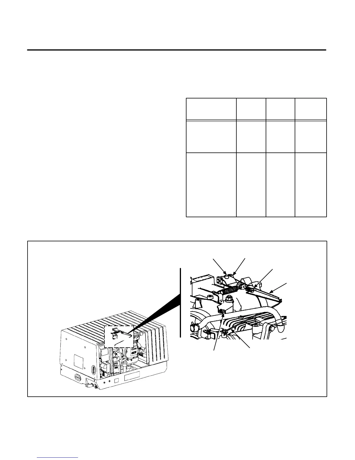
GOVERNOR
LINKAGE
SPEED
ADJUSTMENT
SCREW
GOVERNOR
ARM
SENSITIVITY
ADJUSTMENT
SCREW
MOUNTING
BOLT
GOVERNOR
SHAFT
FIGURE 8-7. GOVERNOR ADJUSTMENTS
 Loading...

