10-7
Valve Clearance Adjustment
The valve clearance can be checked and adjusted.
Adjust the valve clearance only when the engine is
at ambient temperature.
1. Follow head cover removal instructions in the
Head Cover
section on Page 10-2. Inspect
the valve stems for proper alignment with the
rocker arms.
2. Advance the engine until both of the valves are
closed and there is no pressure on the valve lift-
ers (piston at top dead center).
3. Clearances are shown in Section
3.
Dimen-
sions and Clearances
. For each valve, the
gauge should just pass between the top of the
valve stem and the rocker arm. (See Figure
10-11.)
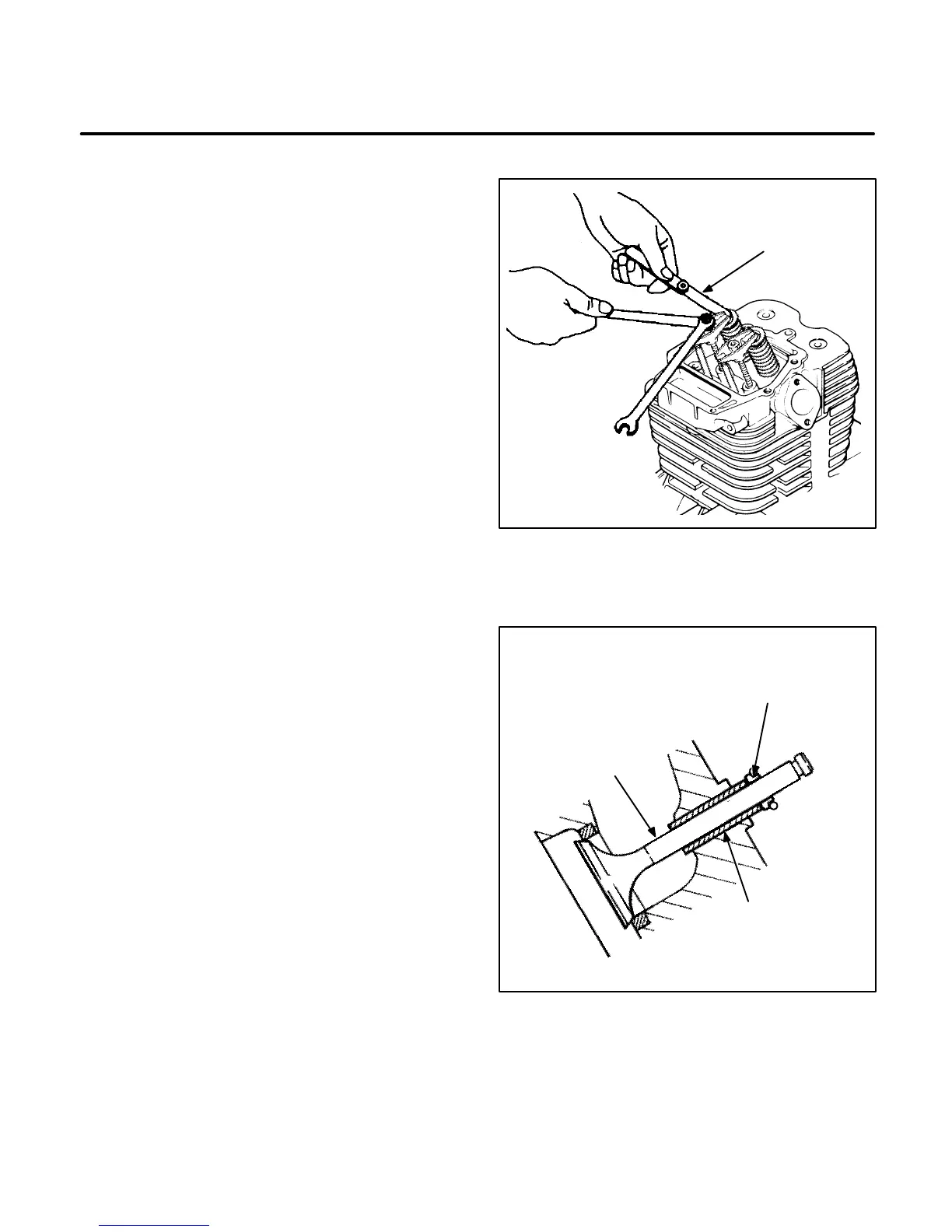
4. To correct the valve clearance, place a wrench
on the adjusting nut and a wrench on the outer
locking nut. Loosen the outer locking nut and
turn the adjusting nut as needed to obtain the
correct clearance. Tighten locking nut after ad-
justment is made.
5. Recheck the valve clearance after adjustment
has been made and also check the rocker arm
bolts to see that they have not loosened as a re-
sult of adjusting the valve lash.
6. Reinstall the head cover and torque the head
cover bolts to the specified torque.
Intake Valve Seal Replacement
A worn or cracked intake valve seal can cause high
oil consumption and spark plug fouling. Replace a
defective intake valve seal as follows:
1. Pull the old valve seal out carefully to avoid
damaging the valve guide.
2. Coat the intake valve stem with engine oil and
insert it into the valve guide.
3. Press the valve seal into the valve guide by
hand until the shoulder of the seal rests against
the cylinder head (Figure 10-12).
FEELER
GAUGE
FIGURE 10-11. VALVE CLEARANCE ADJUSTMENT
VT1043-1s
VALVE
SEAL
INTAKE
VALVE
VALVE
GUIDE
FIGURE 10-12. VALVE SEAL INSTALLATION
 Loading...

