6-12
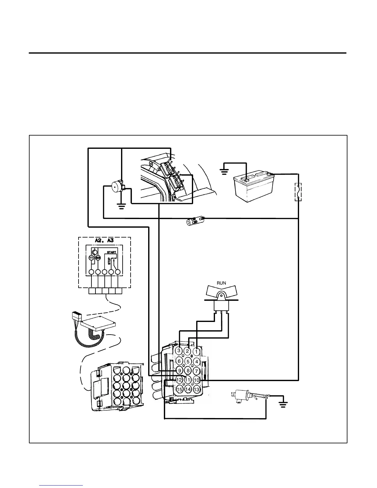
Spec A Battery Charge Mode
With the genset running, AC voltage is produced in the B1-B2 windings for the battery charge circuit.
• The AC output voltage from the B1-B2 winding is converted to DC voltage when it passes through the full-wave
rectifier bridge (CR1). The voltage is then supplied through battery charge resistor (R1). The 12-volt DC output
(one-ampere maximum) is used to power the control assembly (A1), fuel pump (E2), the remote control, and to
prevent discharge of the genset starting battery during genset operation. This output is not sufficient to charge
a low or dead battery.
ES2017-4s
BATTERY BT1
FUSE F1
CONTROL ASSEMBLY A1
START/STOP SWITCH S1
BRIDGE
RECTIFIER
CR1
BATTERY CHARGE
RESISTOR R1
FUEL PUMP E2
REMOTE CONTROL
STATOR
CONNECTORS
B2
B1
J1 CONNECTOR
P1 CONNECTOR
A
BCEF
FIGURE 6-7. SPEC A BATTERY CHARGE MODE
 Loading...

