8-23
Checking and Adjusting Regulator Lock-off
Pressure:
Lock-off pressure is determined as fol-
lows by pressurizing the back (vent) side of the reg-
ulator diaphragm to simulate carburetor venturi
vacuum:
1. Connect the regulator inlet (Figure 8-18 on
Page 8-22) to a source of air pressure regu-
lated to 11 inches WC (280 mm WC).
2. Disconnect from the carburetor the LPG supply
hose, which comes from the regulator.
3. “T” in two hoses to the end of the hose con-
nected to the regulator vent fitting (3/8 inch
I. D.). Use one hose to measure pressure by
connecting it to an inclined manometer that
reads 0 to 2 inches WC (0 to 50 mm WC) and
the other to provide the test pressure.
4. Attach a soap bubble to the end of the LPG
supply hose which was disconnected from the
carburetor. While reading the pressure indi-
cated by the manometer and watching the
soap bubble, blow lightly into the hose being
used to pressurize the regulator. Regulator
lock-off pressure is the minimum pressure that
will cause air to flow through the regulator, as
indicated by the expanding soap bubble. (At
first the soap bubble may expand due to dia-
phragm movement but will stop expanding if air
is not flowing through the regulator.)
CAUTION
If this is a bench test of the reg-
ulator, make sure the diaphragm is in a ver-
tical plane (as in the genset), otherwise the
weight of the diaphragm will cause erro-
neous readings of lock-off pressure.
•
For Gensets Beginning Spec E:
Replace the
demand regulator assembly if the lock-off pres-
sure does not fall between 0.10 and 0.30 inch-
es WC (2.5 and 7.6 mm WC).
•
For Gensets Prior to Spec E:
Adjust lock-off
pressure as follows:
• If the lock-off pressure is greater than 0.30
inches (7.6 mm) WC, loosen the lock nut
on the lock-off adjusting screw and back
out the screw (counterclockwise) until the
lock-off pressure falls between 0.10 and
0.30 inches WC (2.5 and 7.6 mm WC). Set
the adjusting screw locknut and test lock-
off pressure again. Repeat the procedure
if necessary.
• If the lock-off pressure is less than 0.10
inches WC (2.5 mm WC), loosen the lock
nut on the lock-off adjusting screw and turn
in the screw (clockwise) until the lock-off
pressure falls between 0.10 and 0.30 inch-
es WC (2.5 and 7.6 mm WC). Set the ad-
justing screw locknut and test lock-off
pressure again. Repeat the procedure if
necessary.
• Replace the demand regulator if it contin-
ues to leak after lock-off pressure adjust-
ments have been attempted.
Priming Solenoid Test:
Upon completing the lock-
off pressure test, energize the priming solenoid by
connecting battery positive (+) to the orange lead
and battery negative (–) to the green lead. Replace
the regulator assembly if the priming solenoid does
not cause the regulator to open.
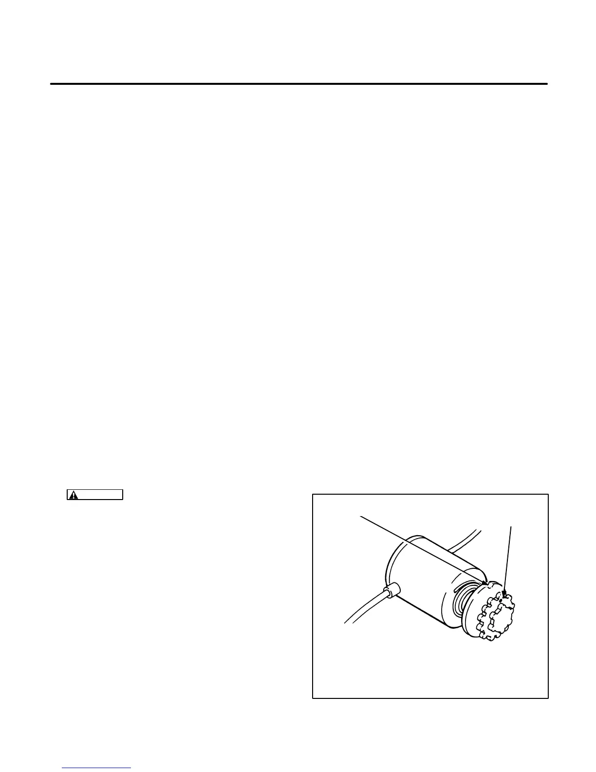
Priming Solenoid Adjustment:
See Figure 8-19.
If the genset does not start when it is hot, rotate the
dial counterclockwise—the fuel mixture could be
too rich. If the genset does not start when it is at am-
bient temperature, rotate the dial clockwise—the
fuel mixture could be too lean.
Adjust the primer solenoid by holding on to the metal disk
and rotating the red dial. Turn the dial clockwise to obtain a
richer mixture and counterclockwise to obtain a leaner
mixture.
METAL DISK RED PLASTIC
DIAL
FIGURE 8-19. AUTOMATIC PRIMING SOLENOID
 Loading...

