7-8
Resistor (R1) – Spec A Only
The battery charge resistor can be checked with an
ohmmeter. Disconnect the leads from the resistor
and measure the resistance between terminals on
one end to the resistor and the terminals on the oth-
er end. The resistor should measure between 4 and
6 ohms. If an abnormal reading is measured, re-
place the resistor.
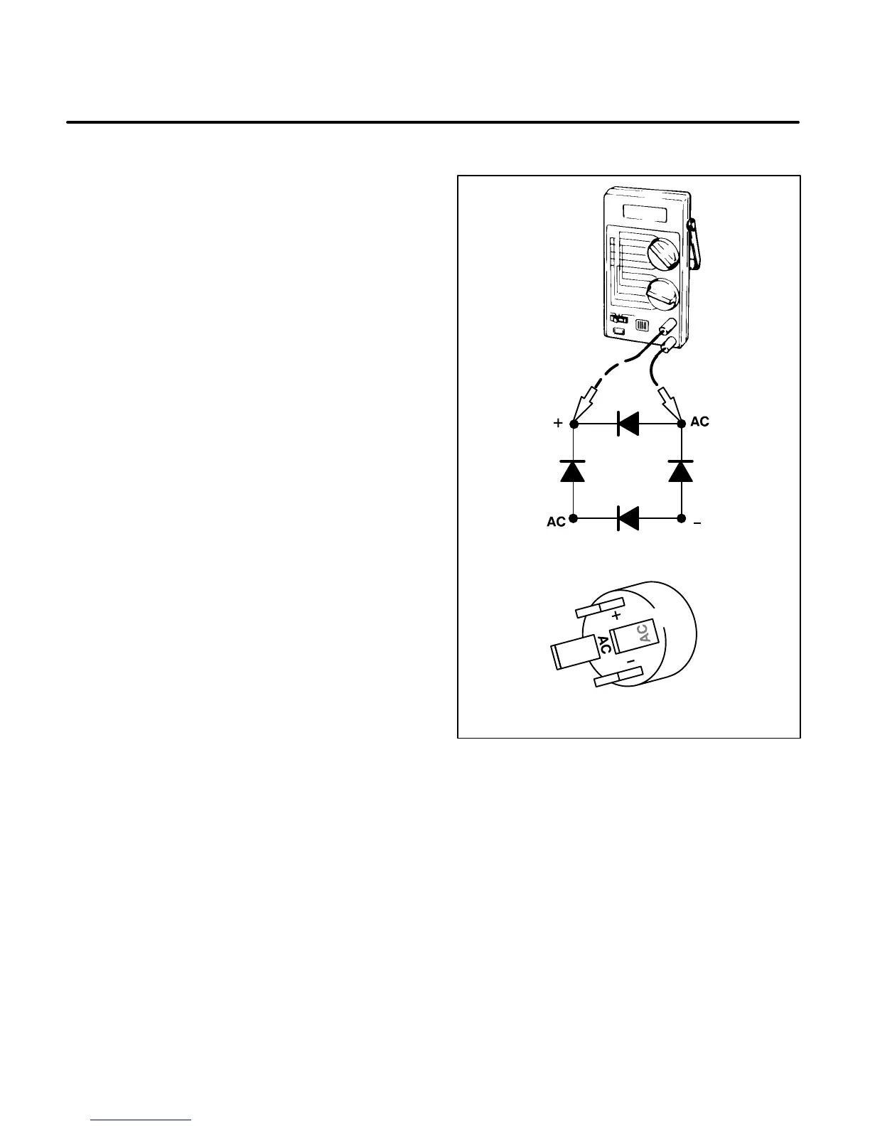
Diode Bridge (CR1)
The diode bridge consists of four diodes connected
in a bridge circuit (Figure 7-6). The diode bridge can
be checked with a diode checker. Remove all of the
leads from the diode bridge and check each diode
individually. Continuity should be indicated in the
forward bias direction and an open circuit should be
indicated in the reverse bias direction (refer to your
meter instruction manual). If any of the diodes
check bad, replace the diode bridge.
BRIDGE RECTIFIER SCHEMATIC
SPEC A BRIDGE RECTIFIER CR1
ES2015s
FIGURE 7-6. DIODE BRIDGE CR1 CHECK
 Loading...

