10-8
CRANKCASE COVER
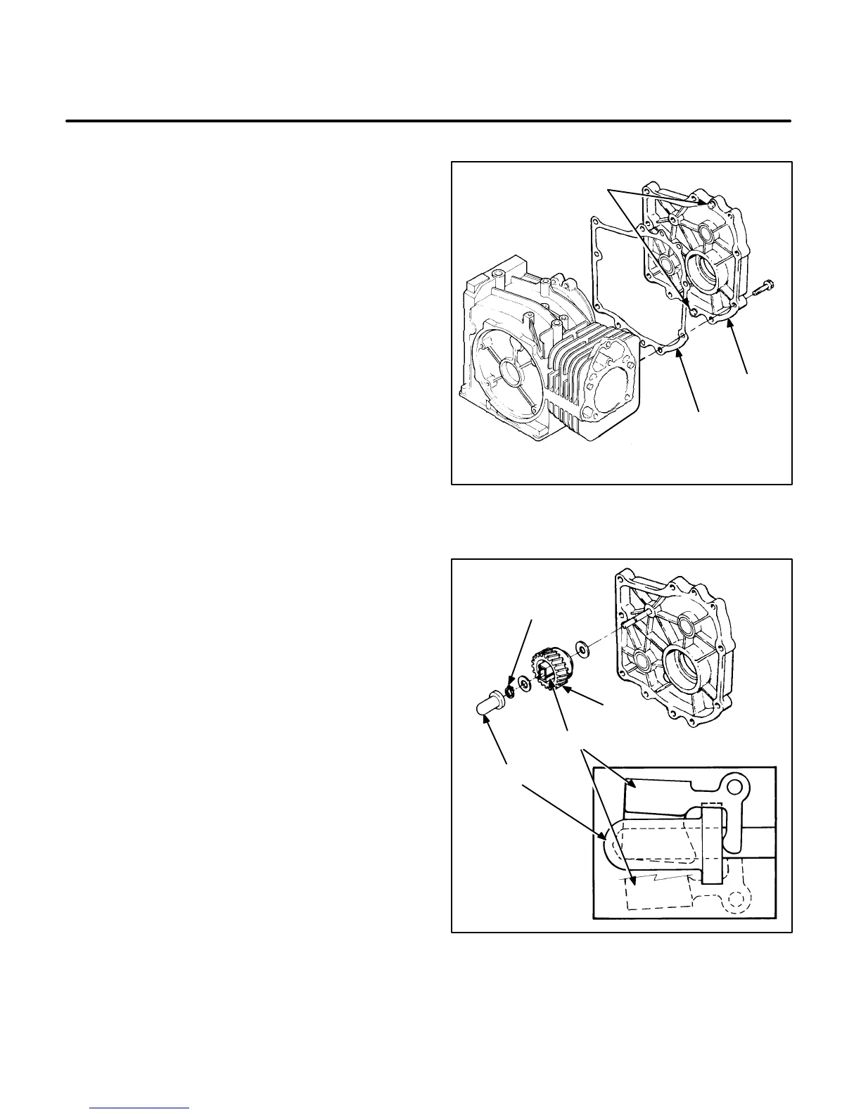
1. The crankcase cover is located in two places
with dowel pins (Figure 10-13). Do not attempt
to pry the crankcase cover off or damage can
result. Remove the crankcase cover mounting
bolts. Hold the crankcase cover and lightly tap
the end of the crankshaft with a plastic ham-
mer.
2. Remove the crankcase cover very carefully to
prevent the shaft from scraping the lip surface
of the oil seal.
3. Remove and tag shims from the crankshaft,
camshaft, and balancer shaft. Shim thick-
nesses differ and they must be reassembled in
their original positions.
4. Make sure the governor shaft is properly posi-
tioned when installing the cover. Use a new
gasket and clean the crankcase cover and the
engine block gasket mating surfaces. Place
crankcase cover in position and secure all bolts
in a star pattern to the specified torque (see
Section
4.
Torque Specifications
).
GOVERNOR
With the crankcase cover removed, the governor
can be inspected or disassembled for service. The
governor assembly must spin freely on the center
pin without excessive looseness or wobble. Sleeve
tip wear is the most common cause of governor fail-
ure. Check for flat spots on the sleeve tip. If the gov-
ernor sleeve, gear, or flyweights are worn or other-
wise damaged, replace them.
To disassemble, remove the snap ring from the gov-
ernor center pin and slide the governor gear assem-
bly off the mounting shaft. Be careful not to lose the
outer washer. See Figure 10-14. To install the gov-
ernor, assemble in reverse order of removal (see in-
set drawing, Figure 10-14, for position of flyweight
and sleeve). The snap ring can be installed by plac-
ing it over the end of the shaft, then use the sleeve to
push it into position. To remove the governor shaft,
remove the retainer clip outside the block and then
lower the governor shaft into the crankcase.
C1113-1s
GASKET
CRANKCASE
COVER
KNOCKOUT
PINS
FIGURE 10-13. CRANKCASE COVER
GEAR
SNAP RING (RUBBER
WASHER BEGIN
SPEC E)
SLEEVE
FLYWEIGHTS
FIGURE 10-14. GOVERNOR
 Loading...

