9-9
Test A:
Connect a DC voltmeter into the back side
of the voltage regulator connector J4 as follows: At-
tach the positive (+) meter lead to J4 pin 7 and the
negative (–) meter lead to J4 pin 3.
Push the start switch and observe the voltmeter
reading. If approximately 12 VDC is measured field
flash voltage is available, proceed to Test B. If no
voltage is measured, check for a poor connection at
the P4-J4 connectors and at the P1-J1 connectors.
If connections check good, refer to Section
6. Trou-
bleshooting
for procedures.
Test B:
Move the positive (+) meter lead to pin 9 and
connect the negative (–) meter lead to pin 10.
Start the genset and allow engine speed to stabi-
lize. Measure the field voltage with no load applied
and then with full load applied. If both readings fall
within a range of 40 VDC no load to 100 VDC full
load, voltage build up is OK and the brushes, rotor
and stator are working properly.
If no voltage is measured when the start switch is
pushed, proceed to the
Voltage Regulator (VR1)
Test
on Page 9-12.
If 7 to 13 VDC is measured when the start switch is
pushed and the genset stops running when the
switch is released, proceed to Test C.
Test C:
Disconnect the voltage regulator connector
plug J4 from the harness connector P4. Attach an
AC voltmeter to the generator output leads L1 and
L2. Apply 12 VDC to the P4 connector at pins 9
(positive [+]) and 10 (negative [–]).
Start the genset and observe the voltmeter reading.
If approximately 40 VAC is measured, the generator
brushes, rotor, and stator are working properly, pro-
ceed to the
Voltage Regulator (VR1) Test
on Page
9-12.
If no voltage is measured, proceed to
Brushes and
Slip Rings
on Page 9-12.
Rotor Test
The rotor can be tested for grounded, open, or
shorted windings using an ohmmeter. Figure 9-7,
and Figure 9-8 on Page 9-10 show the rotor re-
moved from the genset for testing. The rotor can be
tested without removing it from the generator. To
gain access to the slip rings, follow the
Generator
Disassembly / Base Removal
procedures on Page
9-2 through the fan hub assembly removal proce-
dure. Use a stiff wire to hold the brushes off the slip
rings during testing. Refer to the
Brushes and Slip
Rings
section on Page 9-12 for the procedures for
inserting the wire.
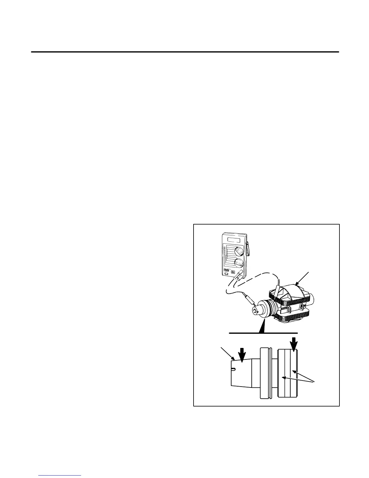
Ground Test:
Set the ohmmeter to the highest re-
sistance scale or use a megger. Touch one test prod
to the rotor shaft and hold it there. Touch the other
test prod to one of the slip rings as shown in Figure
9-7 on Page 9-9. A reading of infinity should be
measured. A reading of less than one megohm (one
million ohms) indicates the rotor is grounded. Re-
place a grounded rotor with a new rotor.
ES1764-1s
ROTOR
SHAFT
ROTOR
SLIP
RINGS
FIGURE 9-7. GROUNDED ROTOR TEST
 Loading...

