10-9
CAMSHAFT, TAPPET AND BALANCER
REMOVAL
1. Place the engine cylinder down on a clean flat
surface (Figure 10-15).
2. Carefully pull out the camshaft assembly.
3. Remove the valve tappets. Mark the tappets
because tappet clearances differ and the tap-
pets must be reassembled in their original posi-
tions.
4. Pull out the balancer shaft assembly.
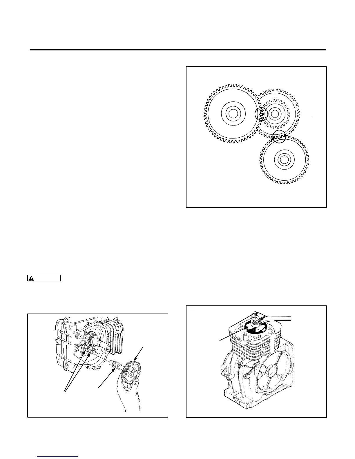
5. For installation, apply oil to the tappets and the
tooth surface of the gears. Align the marks on
the cam gear and crank gear and also on the
balancer gear and crank gear as shown in Fig-
ure 10-16.
PISTON AND CRANKSHAFT
The piston assembly consists of the piston, piston
pin, and connecting rod assembly. After piston re-
moval, all parts must be carefully inspected for
damage and wear before reinstalling. Remove the
carbon from the top of the cylinder bore and check
for a ridge. Remove ridge with a ridge reamer (see
Figure 10-17) before attempting piston removal.
Remove the piston as follows:
CAUTION
Improper use of a ridge reamer can
damage the cylinder bore. Follow tool manufac-
turer’s instructions and be careful when using a
ridge reamer.
C1133-1s
CAM GEAR
TAPPETS
CAMSHAFT
FIGURE 10-15. CAMSHAFT AND TAPPETS
CAM GEAR
BALANCER GEAR
CRANK GEAR
FIGURE 10-16. CAM, CRANK AND BALANCER
GEAR ALIGNMENT
CT1090-1s
RIDGE
REAMER
FIGURE 10-17. REMOVING WEAR RIDGE
 Loading...

