6-6
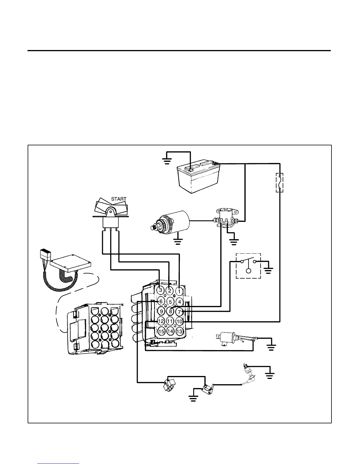
Spec A Start - Ignition Mode
Holding the Start/Stop switch (S1) in the Start position activates the following ignition circuit:
• Control assembly (A1) enables the ignition circuit to open a ground path through the control assembly to the
magneto assembly (G2) so that output from the magneto will energize the ignition coil (T1).
• With the engine cranking, a permanent magnet in the flywheel rotates, at the proper time, past the magneto
to induce a voltage at the ignition coil (T1) that fires the spark plug (E1) for ignition.
• Battery positive (B+) is supplied to the fuel pump (E2) or fuel shutoff solenoid (E2) and regulator(K2) on LPG
models. (Schematic for gasoline fueled model shown.)
ES2017-1s
STARTER MOTOR B1
BATTERY BT1
FUSE F1
START
RELAY K1
CONTROL ASSEMBLY A1
START/STOP SWITCH S1
SPARK PLUG E1
IGNITION
COIL T1
MAGNETO
IGNITION G2
OIL LEVEL
SWITCH S2
FUEL PUMP E2 (FUEL SHUTOFF
SOLENOID ON LPG MODEL)
J1 CONNECTOR
P1 CONNECTOR
FIGURE 6-4. SPEC A START – IGNITION MODE
 Loading...

