8-30
1. Place a spring washer and a flat washer on the
shaft, as shown in Figure 8-29.
2. Place the mounting bracket on the motor with
the through-bolt lead-ins to the inside of the
motor. The “flat” near one mounting hole
should line up with the positive stud on the end
cap, so the through-bolts line up.
3. Insert the through-bolts, and torque to 35-45 lb-
in. (3.96 - 5.09 Nm).
4. Wipe dust from the helix and gear, and apply a
light coat of GE Versilube 322-L to the outside
diameter of the helix, the inside diameter of the
gear and the unchamfered end of the gear.
Place the clutch and helix assemblies on the
motor shaft, with flats engaged in the clutch
hole.
5. If the return spring is unassembled:
A. Place a 1-1/16 inch O.D. washer over the
end of the shaft.
B. With the chamfered side of the shaft hole
facing up, place a plastic retainer on the
shaft and line up the hole with a hole in the
shaft.
C. Support the plastic retainer with a vise or
other solid surface. Using a 5/32 or 1/8
inch nail set and hammer, drive in a new
roll pin. The pin should be driven about
1/10th of an inch (2.5 mm) from the edge
of the plastic retainer, or in such a way that
it is evenly spaced from each side.
D. Place the spring cover over the top of the
plastic retainer, then place the return
spring on top of the retainer.
E. With a washer placed over the point of the
plastic retainer, push the metal retainer
into the hole of the plastic retainer as far as
it will go.
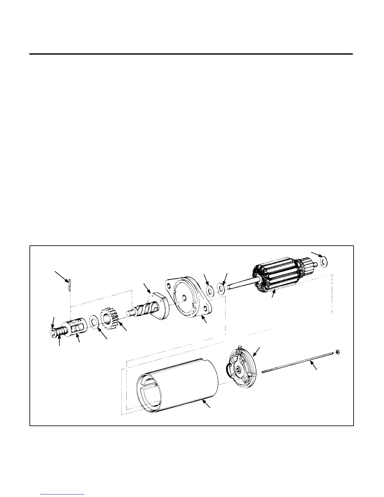
METAL SPRING
RETAINER &
WASHER
ROLL
PIN
CLUTCH & SPLINE
ASSEMBLY
FLAT
WASHER
SPRING
WASHER
WASHER
ARMATURE
BRUSH
ENDCAP
THROUGH
BOLT
MAGNETIC
HOUSING
MOUNTING
BRACKET
GEAR
11/16 INCH
WASHER
SPRING
RETURN
COVER
RETURN
SPRING
ES-1613-1s
FIGURE 8-29. STARTER ASSEMBLY
 Loading...

