10-17
PISTON AND CRANKSHAFT
INSTALLATION
Lubricate the bearings with engine oil. Slide the
crankshaft into the bearing and add shim(s). Install
the crankcase cover and check to see that the
crankshaft turns freely. Measure the side clearance
of the crankshaft as follows:
Side Clearance of Crankshaft
1. Set a dial gauge, as shown in Figure 10-33,
push the shaft in and measure the clearance.
2. If the side clearance exceeds the allowable lim-
its, adjust with shims.
Remove the crankcase cover and assemble the
piston to the connecting rod. Heat the piston to
300
°F (149°C). Position the piston on the connect-
ing rod. Install the piston pin. Install the lock rings on
each side of the piston pin.
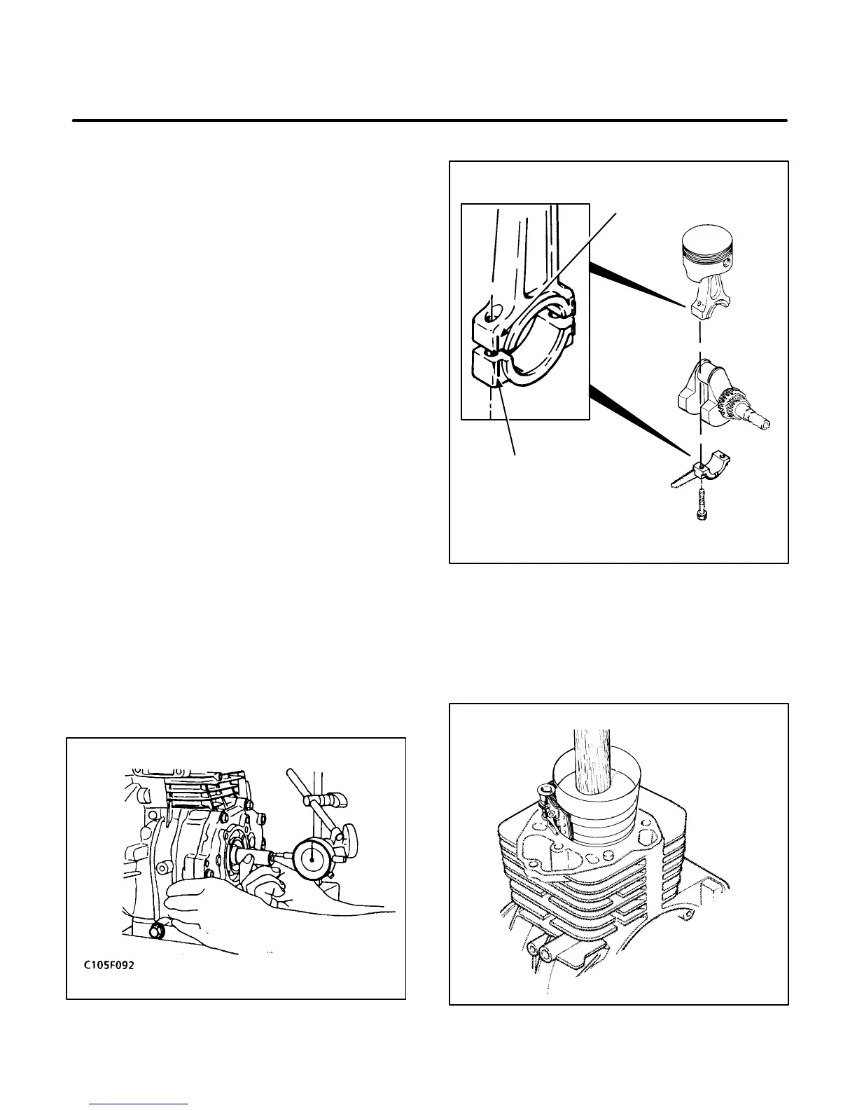
Installing the Piston in Cylinder:
When installing
the piston assembly, observe the markings on the
connecting rod, cap and splasher. See Figure
10-34.
1. Turn the crankshaft to position the crankpin at
the bottom of its stroke.
2. Lubricate the piston assembly and inside of cyl-
inder wall. Compress the rings with a ring com-
pressor as shown in Figure 10-35.
3. Tap the piston down into the bore with the han-
dle end of a hammer until the connecting rod is
seated on the crankpin.
FIGURE 10-33. SIDE CLEARANCE OF
CRANKSHAFT
CT1091-1s
CAP
MARK
CONNECTING
ROD MARK
FIGURE 10-34. ROD CAP ASSEMBLY
CT1066-2s
FIGURE 10-35. INSTALLING PISTON
 Loading...

