10. Engine Block Assembly
10-1
INTRODUCTION
This section covers service procedures for the en-
gine block assembly. A leak down test can be per-
formed to determine the condition of the engine.
Use the procedures in the following section to per-
form the leak down test.
Performing any major service will require genset re-
moval from the vehicle (see
Set Removal Guide-
lines
on Page 5-2). To gain access to the engine
block assembly, the generator and primary engine
systems must be removed. Refer to the previous
sections for the disassembly procedures.
A suggested order of disassembly for the engine
block follows:
1. Oil pan and oil level switch
2. Head cover and breather
3. Rocker arms and push rods
4. Cylinder head, valve springs and valves
5. Crankcase cover, camshaft and balancer
6. Connecting rod and piston
7. Crankshaft and governor lever shaft
LEAK DOWN TEST
Perform the leak down test if performance problems
or high oil consumption occur and poor compres-
sion is suspected. Follow each of these steps and
refer to the test equipment manufacturer’s instruc-
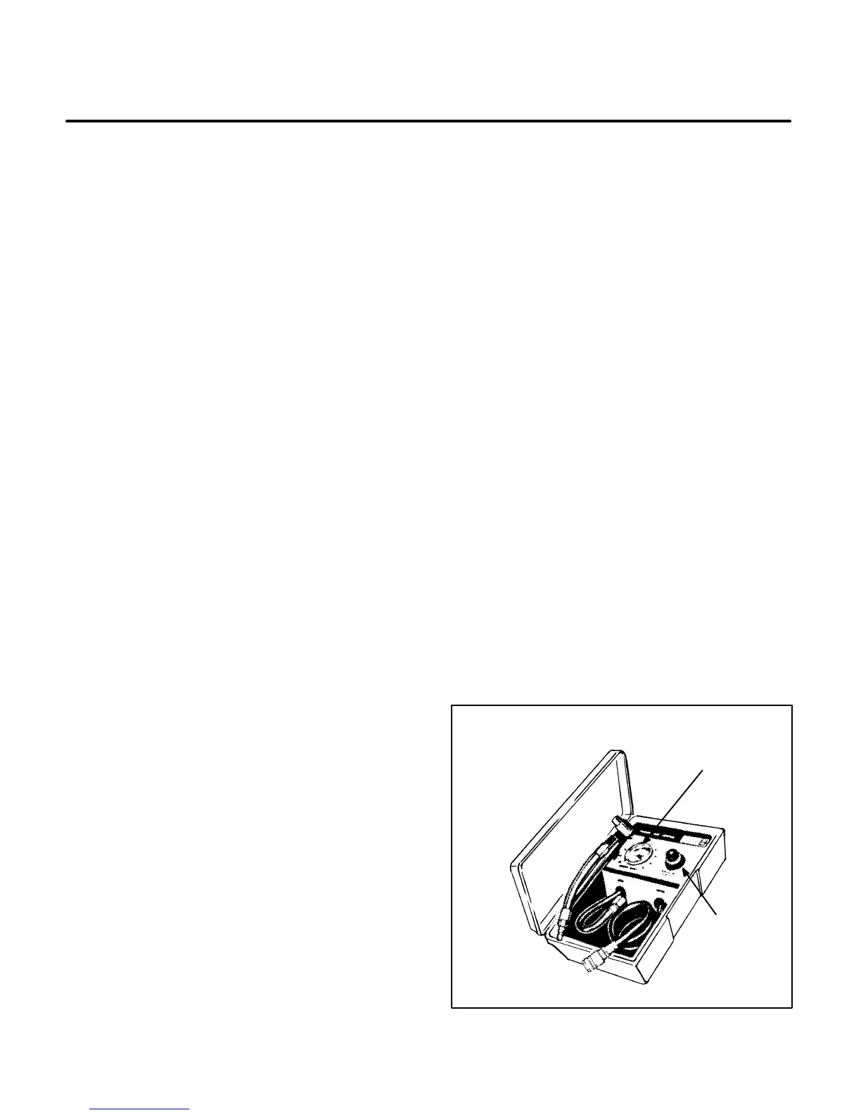
tions. A typical tester is shown in Figure 10-1.
1. Start the engine and allow it to warm up for ten
minutes. If the engine will not start, continue to
the next step.
2. Disconnect the battery negative (–) cable to
prevent accidental starting and remove the
spark plug.
3. Manually rotate the the engine in the direction
of normal operation by turning the fan hub as-
sembly. Stop turning the engine when it reach-
es top dead center (T.D.C.) on the compression
stroke. T.D.C. can be determined by:
A. Removing the head cover and observing
the valve overlap on the compression
stroke.
B. Feeling compression air escaping the
spark plug hole.
C. Using a tester with a T.D.C. indicator fea-
ture.
4. Connect the tester to shop air and set calibra-
tion. Perform the leak down test according to
the manufacturer’s instructions. Secure the
fan wheel to prevent the piston from moving
during this test.
5. Screw the air fitting into the spark plug hole. At-
tach plug fitting to tester.
6. The tester needle indicates the percentage of
cylinder leakdown. The following describes the
general condition of the engine:
• 0-10 Percent leak down – Excellent condi-
tion
• 10-20 Percent leak down – Normal condi-
tion
• 20-30 Percent leak down – Nearing ser-
vice limit
7. If leakage is greater than 30 percent, the en-
gine could need major service work. With the
tester still connected, listen for air leakage at
the points listed in Table 10-1 on Page 10-2
and note probable cause of the engine prob-
lem.
AIR LEAKAGE
GAUGE
REGULATOR
M1907s
FIGURE 10-1. TYPICAL LEAK DOWN TESTER
 Loading...

