6-21
WARNING
Many troubleshooting procedures present hazards that can result in severe personal inju-
ry or death. Only qualified service personnel with knowledge of fuels, electricity, and machinery haz-
ards should perform service procedures. Review safety precautions on page iii.
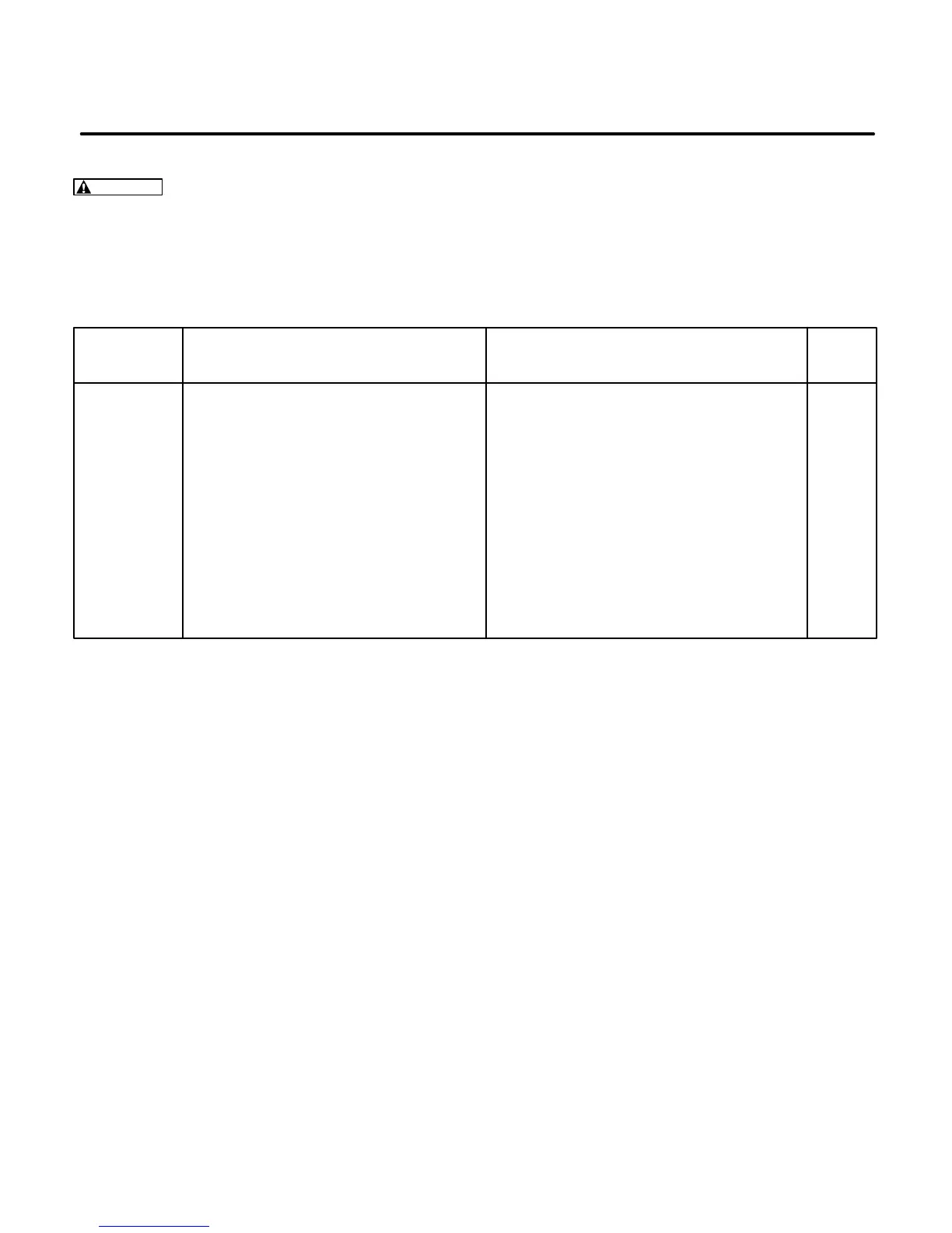
TABLE 6-9. BEGIN SPEC B CONTROL TROUBLESHOOTING – FIELD FLASH MODE
Trouble Possible Cause Corrective Action Section/
Page
Engine Starts 1. Low oil level. 1. Check oil level and add oil if low.
But Stops 2. Defective low oil level switch 2. Disconnect low oil level switch and 10-2
When Start (Spec B-F, if applicable). check set operation. Replace if defective.
Switch Is 3. No field flash voltage due to: 3a. Check wiring continuity to the brush 9-8
Released a. Open circuit in wiring. block F1-F2, voltage regulator VR1,
b. Brushes not making good contact control assembly A1 and generator
with slip rings. B1-B2 (50 Hz) and Q1-Q2 windings.
c. Slip ring surface is rough or pitted. Check connections of P5 and P6
connectors on the generator housing.
3b. Check brushes for wear and for contact 9-12
with the slip rings.
3c. Check the slip rings.
4. Defective generator, control assembly 4. Perform field voltage test. 9-8
A1, or voltage regulator VR1.
 Loading...

