8-7
Ignition Coil Ohmmeter Check:
Remove the con-
trol panel mounting screw (Torx T-30) to access the
ignition coil. Check the ground lead for continuity
between the ground lead terminal and a clean
ground point on the intake manifold.
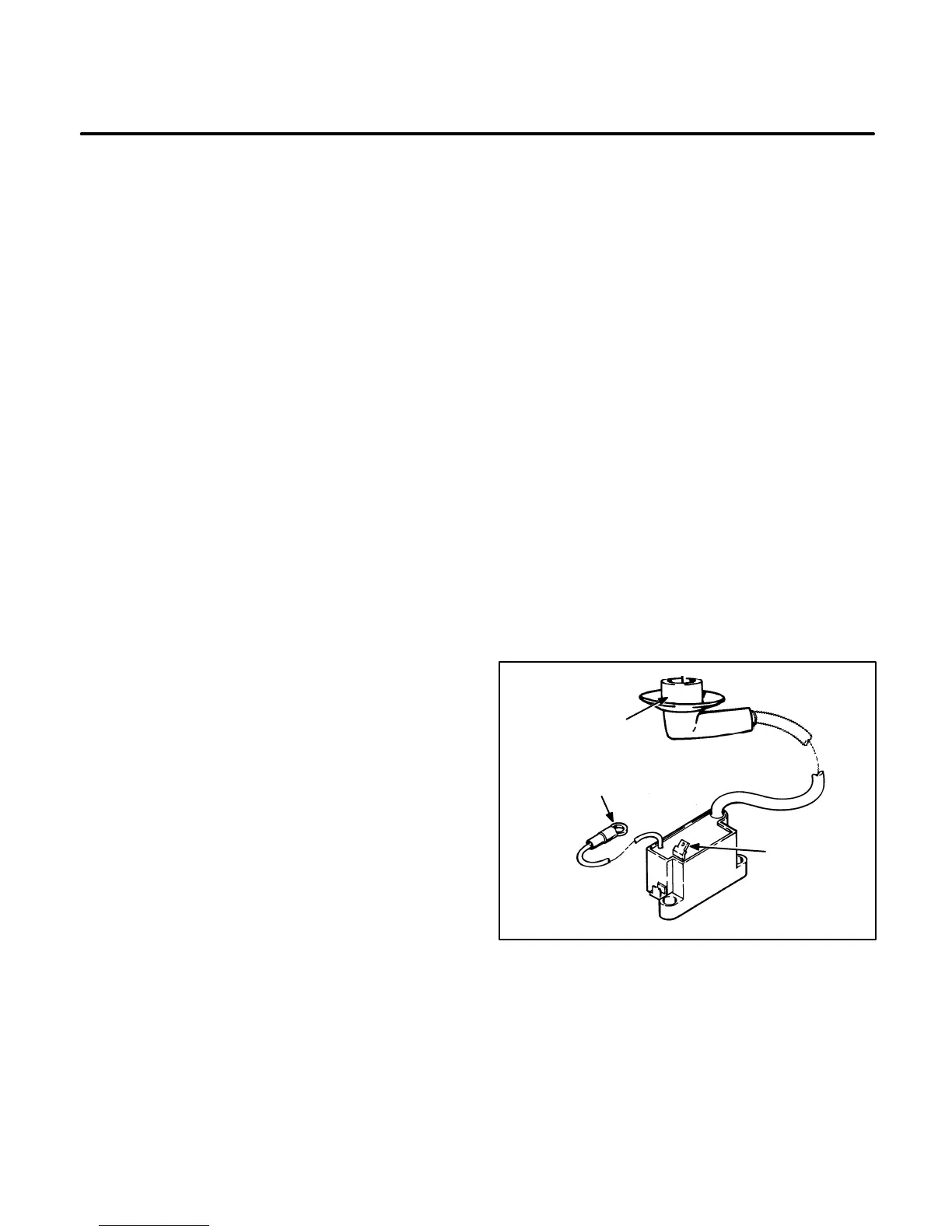
Disconnect the spark plug lead from the spark plug
and disconnect the primary lead from the terminal
on the coil. Remove the ignition coil mounting
screws and remove the ignition coil from the genset
for testing. See Figure 8-5.
1. Inspect the terminal and leads for signs of cor-
rosion or looseness and look for cracks or other
damage. Look for evidence of electrical leak-
age around the high tension connection (indi-
cated by carbon tracking). Replace a coil with
any defects.
2. Measure the primary winding resistance. Con-
nect one ohmmeter lead to the primary terminal
and the other lead to the ground lead ring termi-
nal. The resistance should be approximately
0.5 ohms at 75
°F (24°C). Replace the coil if a
high or low reading is measured.
3. Measure the secondary winding resistance.
Connect one ohmmeter lead to the spark plug
connector, inside the boot, and the other lead
to the ground lead ring terminal. The resistance
should be approximately 1,100 ohms at 75
°F
(24
°C). Replace the coil if a high or low reading
is measured.
If the coil windings check good, proceed to the Igni-
tion Wiring check.
Ignition Wiring
The ignition wiring consists of the following:
• One ground wire connected to the ignition coil
and one ground wire connected to the magneto
assembly.
• One wire from the magneto to the ignition coil
primary.
• One ignition enable wire from the control as-
sembly to the magneto.
• One wire from the low oil level switch to the
control assembly. (Spec A-F only, if applica-
ble.)
• One high tension lead from the ignition coil sec-
ondary to the spark plug.
Refer to the figure in Section
12. Wiring Schematic/
Diagram
that corresponds to your particular genset.
(Do not disassemble the genset to check the mag-
neto wiring at this time.)
Thoroughly inspect the ignition wiring for loose con-
nections and cuts or breaks in the insulation. Test
suspect leads for continuity with an ohmmeter. Use
a megger to check for breaks in the spark plug lead.
Also check control wiring for loose or grounded con-
nections. If any problems are found, correct them
and repeat the ignition spark check. If no problems
are found proceed to the
Magneto Assembly
sec-
tion, following.
ES1767-1s
SPARK PLUG BOOT
(SECONDARY)
PRIMARY
TERMINAL
GROUND LEAD
FIGURE 8-5. IGNITION COIL
 Loading...

