8-12
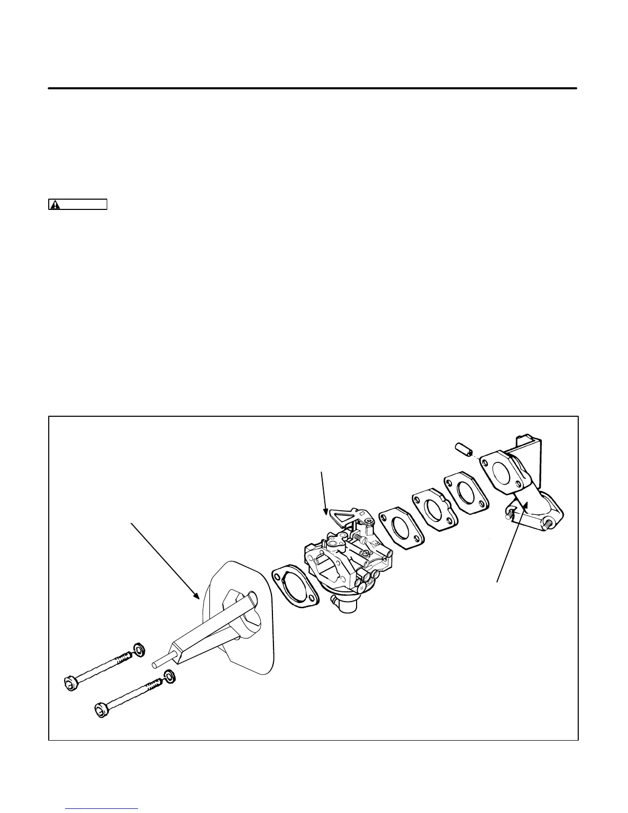
Carburetor and Intake Manifold Assembly
This assembly consists of the carburetor and the in-
take manifold assembly. See Figure 8-9. It is easier
to disconnect the carburetor linkages if the genset
housing is removed.
WARNING
Fuel presents the hazard of fire or
explosion that can cause severe personal injury
or death. Eliminate all possible ignition sources
such as open flame, sparks, cigarettes, pilot
lights, arc-producing equipment, and electrical
switches from the work area and rooms with
common ventilation. Keep a type ABC fire extin-
guisher nearby.
Disassembly:
Use the following procedures to re-
move the carburetor and intake manifold assembly.
1. Disconnect the fuel line and plug it to prevent
fuel spill and fuel vapor accumulation. (Begin
Spec B models: Disconnect the fuel solenoid
leads.)
2. Remove the air filter assembly.
3. Remove the carburetor mounting screws from
the left side of the endbell.
4. Close the choke and throttle plates by rotating
their shafts in a counterclockwise direction.
Pull the carburetor with its gaskets out slowly.
5. Disengage the governor and choke linkages
from the carburetor (it may be necessary to re-
move the automatic choke assembly mounting
screw to remove its linkage).
6. Remove the intake manifold mounting nuts and
lift off the manifold. Remove the intake man-
ifold gasket and plug the intake port with a rag
to prevent loose parts from accidentally enter-
ing the port.
Assembly:
Perform the assembly steps in reverse
order of disassembly. Use new gaskets between
the intake manifold and the engine, between the in-
take manifold and the carburetor, and between the
carburetor and the air cleaner adapter. Do not use
sealer on the gaskets. Tighten the intake manifold
capscrews to the specified torque.
INTAKE
ELBOW
CARBURETOR
ASSEMBLY
AIR FILTER MOUNTING
ASSEMBLY
FIGURE 8-9. CARBURETOR AND INTAKE MANIFOLD ASSEMBLY
 Loading...

