7-5
CONTROL COMPONENT TESTS
The following control component checks can be
made to verify if components are defective. Discon-
nect the starting battery cables, negative (–) cable
first, before performing these tests.
WARNING
Accidental starting or electrical
shock can cause severe personal injury or
death. Disconnect both genset starting battery
cables before performing maintenance. Re-
move the negative (–) battery cable first and
connect it last to reduce the risk of arcing.
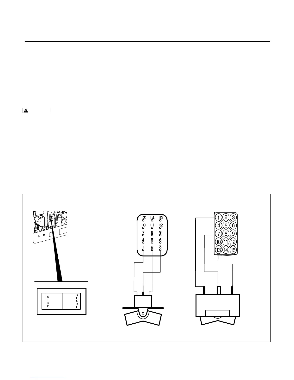
Start/Stop Switch (S1)
Disconnect the P1 (or J1 for Spec B) connector from
control assembly (A1). See Figure 7-3. Continuity
should be measured between pin 1 and pin 3 (pin 13
and pin 7 for Spec B) when the switch is held in the
Start position. Continuity should be measured be-
tween pin 2 and pin 3 (pin 1 and pin 7 for Spec B)
when the switch is held in the Stop position. An open
circuit should be measured between pins 1, 2, and 3
(13, 7 and 1 Spec B) when the switch is in the center
Run position.
If the switch tests good also check the control con-
nector P1 to J1 connections to make sure they are
making a good connection.
If an abnormal reading is obtained, check the conti-
nuity between the connector pins and the switch.
(Use an ohmmeter with pointed test leads to pierce
the insulation at the back of the switch on Spec A
models).
M1899-4s
START/STOP SWITCH S1
SPEC A
P1 CONNECTOR
M1899-4s
BEGIN SPEC B
J1 CONNECTOR
FIGURE 7-3. START/STOP SWITCH
 Loading...

