8-8
Magneto Assembly (G2)
The magneto assembly is a noncontact capacitive
discharge (breakerless) type that is mounted to the
generator endbell. As the engine cranks, two per-
manent magnets on the fan hub assembly pass
very close to the magneto inducing a voltage in two
coils in the magneto. One coil charges a capacitor
that discharges a voltage to the coil when triggered.
The other coil powers the circuit that triggers the
charge circuit. The discharge voltage from the mag-
neto (approximately 16 to 60 VAC when measured
with a digital voltmeter) is supplied to the primary of
the ignition coil.
If no spark was seen in the
Ignition Spark Check
on
Page 8-6 and all accessible ignition wiring checks
good, perform the
Magneto Assembly Check,
next
.
Magneto Assembly Check:
Use a known good
(new) ignition coil.
1. Make sure the cranking circuit and battery are
in good condition.
2. Disconnect the low oil level shut down circuit.
Locate the lead from the low oil level switch that
comes out of the top the oil base below the
spark plug. Separate the in-line quick connect
where lead S2 J1-7 connects to the low oil level
switch.
3. Remove the spark plug, reconnect the spark
plug lead and ground the plug side electrode to
bare metal on the engine.
4. Do not touch the plug or plug wire during test-
ing. Crank the engine and observe the plug. A
good spark should be observed. If no spark is
observed, the magneto or wires connected to
the magneto are the most likely cause. Refer to
Section
9.
Generator
for generator disassem-
bly to access the magneto assembly.
CRANKCASE VENTILATION SYSTEM
The crankcase breather prevents pressure from
building up in the crankcase. It also prevents oil
contamination by removing moisture, gasoline va-
pors and other harmful blow-by materials from the
crankcase. These vapors are routed to the carbure-
tor where they are mixed with the incoming air and
burned in the combustion chamber. A stuck or dam-
aged breather valve can cause oil leaks, high oil
consumption, rough idle, reduced engine power,
and a rapid formation of sludge and varnish within
the engine.
Crankcase Breather Service Procedure
Oil leaks at the seals may indicate that the crank-
case is pressurized. Use the following procedure to
eliminate this condition.
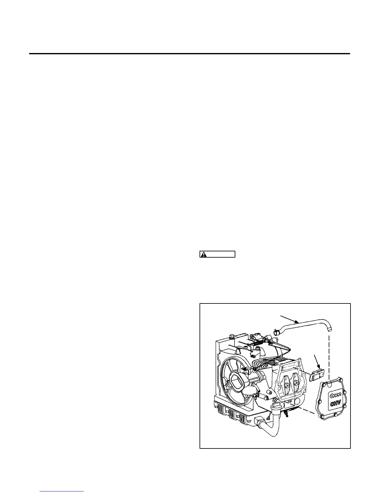
1. Remove the breather tube from the valve cover
(see Figure 8-6).
2. Remove the head cover and breather assem-
bly.
3. Inspect the reed valve. It must be flat with no
signs of creases or other damage. Replace a
defective reed valve. If the breather is dirty,
clean it in parts cleaning solvent.
4. Check the breather tube and air passages for
clogging and clean as required.
WARNING
Most parts cleaning solvents are
flammable and can result in severe personal in-
jury if used improperly. Follow the solvent
manufacturer’s recommendations when clean-
ing parts.
BREATHER HOSE
LS1173-1s
REED
VALVE
FIGURE 8-6. CRANKCASE BREATHER SYSTEM
 Loading...

