7-2
Start Solenoid (K1)
The start solenoid (K1) is used for closing and open-
ing the circuit between the battery and the starter
motor. The start solenoid has heavy duty contacts
that handle the high current draw of the starter dur-
ing cranking.
Control Fuse (F1)
A 5-amp fuse provides protection for the control wir-
ing and remote wiring from a short circuit. The con-
trol fuse is mounted on the front of the control panel.
Circuit Breaker (CB1)
The standard 30-amp circuit breaker protects the
generator AC windings from a short circuit or over-
load. The circuit breaker is located on the control
panel. If an overload occurs, the breaker can be re-
set after all loads are removed from the genset.
Control Assembly (A1)
The control assembly consists of a printed circuit
board with components and relays that are potted
(encapsulated in a nonconductive material) to pro-
tect them from moisture. The control assembly is
mounted near the air inlet for cooling. See Figure
7-1 on Page 7-1 and Figure 7-2.
The control provides the following functions:
• Starter Solenoid Output
• Fuel Pump Output
• AVR Field Flash Output
• Remote Running Output
• Ignition Enable
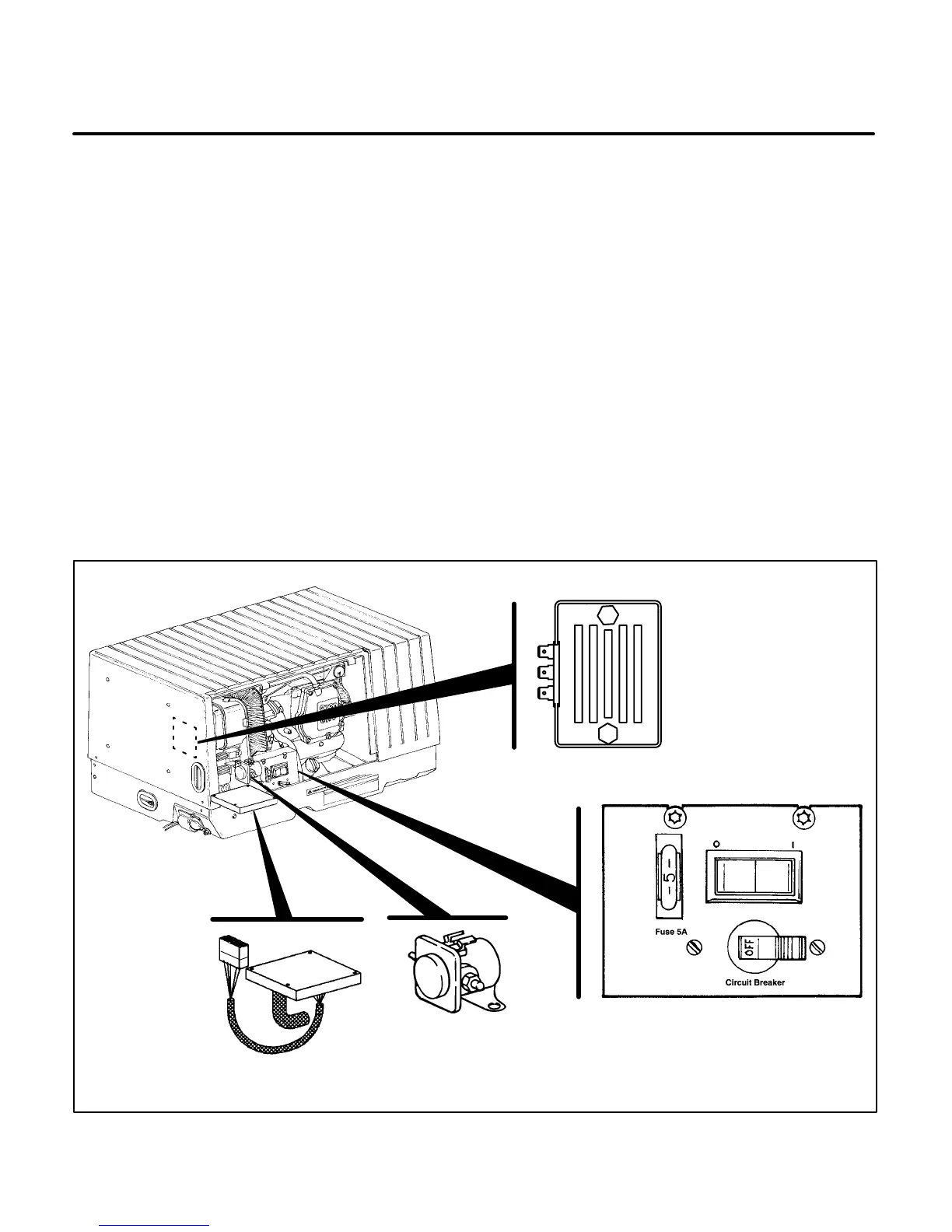
M1899-3s
CONTROL
ASSEMBLY A1
START RELAY K1
BATTERY CHARGER
ASSEMBLY (VR2)
50 HERTZ ONLY
CONTROL PANEL
FIGURE 7-2. BEGIN SPEC B CONTROL COMPONENT LOCATIONS
 Loading...

