145
Menu Mode
11) Setting the input signal format ★ (Used only when the PDA-5002 is installed)
When a video signal is input to INPUT 1 or 2, settings must be made in keeping with peripheral devices in order to
handle RGB and component picture signals.
Make all settings for INPUT 1 and 2 in accordance with the following.
Example:
When reproducing RGB signals = select VIDEO SIGNAL: RGB.
When reproducing signals from DTV set top boxes or DVD players = select VIDEO SIGNAL: COMPONENT.
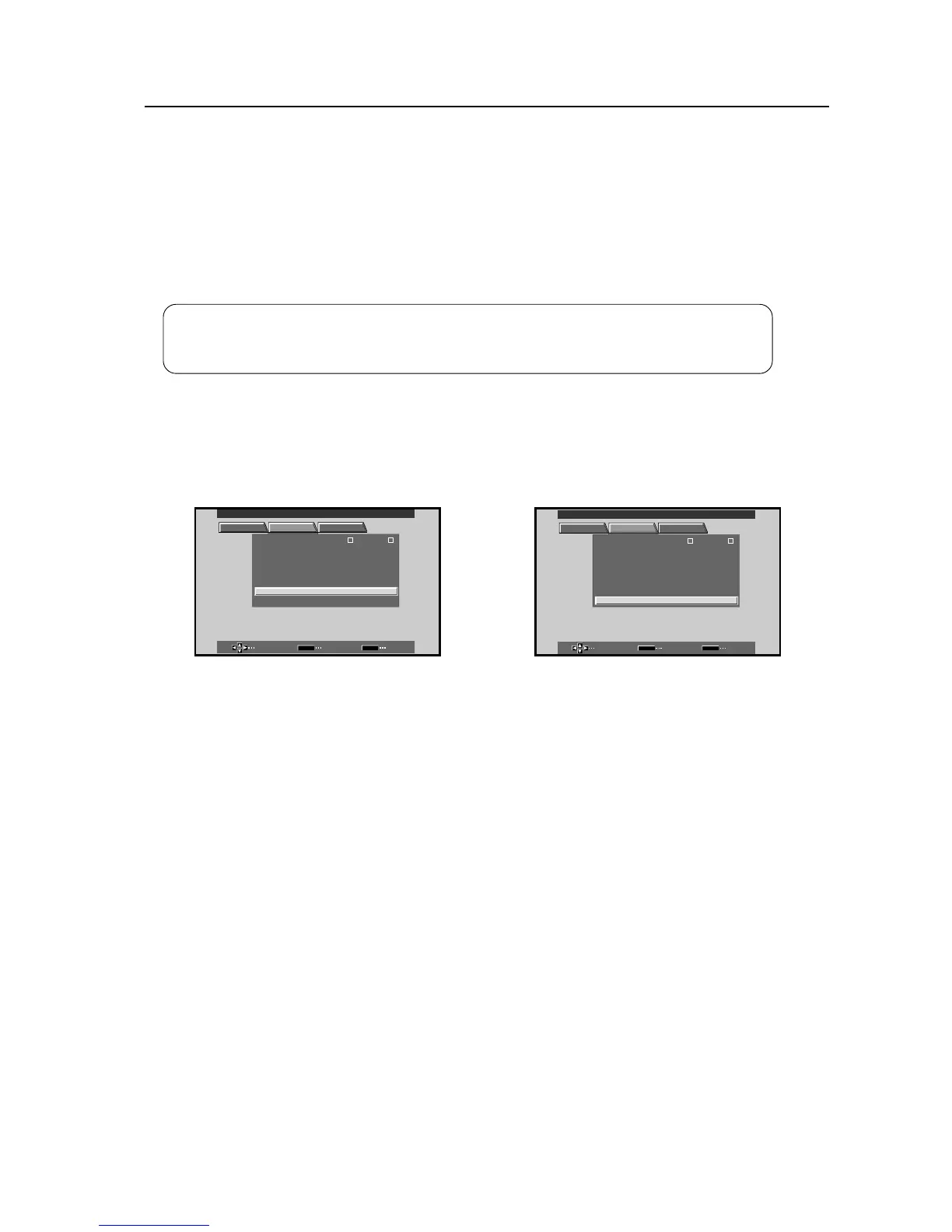
1 Select SET UP.
Screen 1
2 Move the cursor to VIDEO SIGNAL and use the
SET button to change the setting.
Each time the SET button is pressed, the setting
will switch between RGB and COMPONENT.
Screen 2
Set-able condition : INPUT 1 and 2, for video signal input (other than personal computer signals)
Factory preset : INPUT 1: RGB
INPUT 2: RGB
SELECT ENTER EXIT
SET
MENU
PICTURE SET UP OPTION
:
INPUT LEBLA
:
V
IDEO
:
R
GB
:
A
UTO
SETT I N
VIDEO SIGNAL
CLAM
OF FAUT O
P
POWER
G
:
O
FF
PSITIONO
:
L
OWDIGITAL NR
:
O
FFPUREC I N MAE
HIGH CO TNRA TS
:
O
FF
MAIN MENU INPUT1
INPUT
1
SELECT CHANGE EXIT
SET
MENU
PICTURE SET UP OPTION
:
INPUT LEBLA
:
V
IDEO
:
A
UTO
SETT I N
CLAM
OF FAUT O
P
POWER
G
:
O
FF
PSITIONO
:
L
OWDIGITAL NR
:
O
FFPURECI N MAE
HIGH CO TNRA TS
:
O
FF
:
R
GBVIDEO SIGNAL
INPUT
1
MAIN MENU INPUT1
For component video picture signal input, see “5.4.3 Adjustments and settings in the integrator mode”, 7) Setting
component input.
 Loading...