CLUTCH
6.18
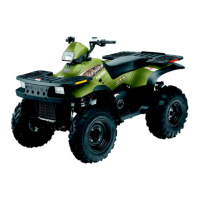
DRIVE CLUTCH ASSEMBLY, CONT.
8. Reinstallcover ,aligning“X”markwithothermarks.
Torque cover bolts evenly to specification.
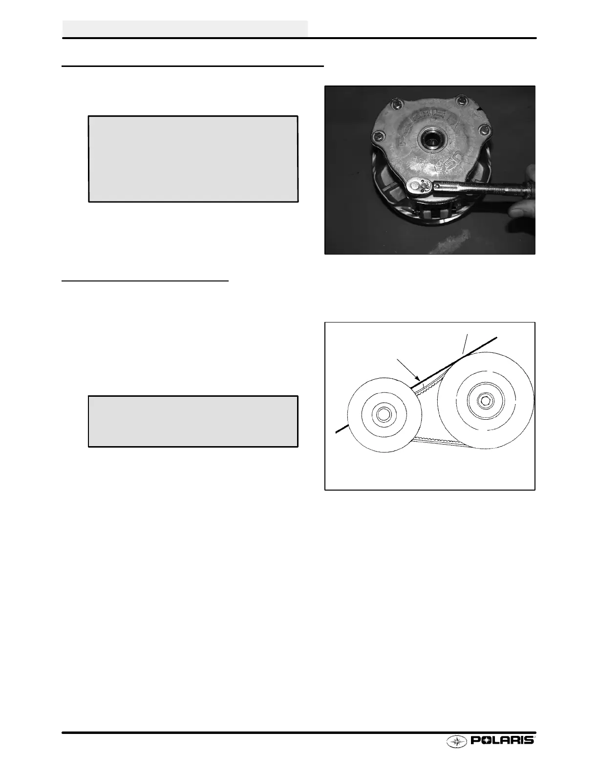
DRIVE BELT TENSION
NOTE: Pinchthesheaveslightlytogetherwithclamptopreventthebeltfrombeingpushedintothedrivensheave.
1. Placeastraightedgeontopofthebeltbetweendriveand
driven clutch.
2. Push down on drive belt until it is lightly tensioned.
3. Measure belt deflection as shown in photo.
If belt deflection is out of specification, adjust by removing or
adding shims between the driven clutch sheaves.
S Remove shims to decrease belt deflection
S Add shims to increase belt deflection
See Driven Clutch Disassembly/Inspection, pages 6.26 -
6.28.
NOTE: Atleastoneshimmustremainbetweentheinnerand
outer sheave of the driven clutch. If proper belt deflection
cannot be obtained, measure drive belt width, length, and
centerdistanceofdriveanddrivenclutch,outlinedinthissec-
tion; all have an effect on belt deflection.
Spider Torque:
200 ft. lbs. (276 Nm)
Cover Screw Torque:
90 in. lbs. (10.4 Nm)
11/8″ (28.5 mm)
Straight Edge
Belt Deflection (Tension):
11/8″ (2.9 cm) - 1 1/4″ (3.2 cm)
 Loading...