CLUTCH
6.21
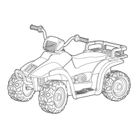
CLUTCH ALIGNMENT
1. Remove belt and install offset/alignment tool as shown.
2. With tool touching rear of driven clutch inner sheave, the
distance at point “A” should be 1/8″.
If the distance is greater than 1/8″ or less than 1/16″,clutch
alignment must be adjusted as follows:
3. Remove drive and driven clutch. See PVT Disassembly,
pages 6.5 - 6.6.
4. Remove PVT inner cover.
5. Loosen all engine mounts. Move front of engine to the
right or left slightly until alignment is correct.
6. T ighten engine mounts and verify alignment is correct.
7. Measure belt deflection and measure offset both above
and below sheave centerlines. Adjust if necessary.
NOTE: On somemodels,minoradjustmentscanbemadeby
adding shims between the frame and front lower left engine
mount to increase the distance at point “A”. If a shim is pres-
ent, it can be removed to decrease the distance at point “A”.
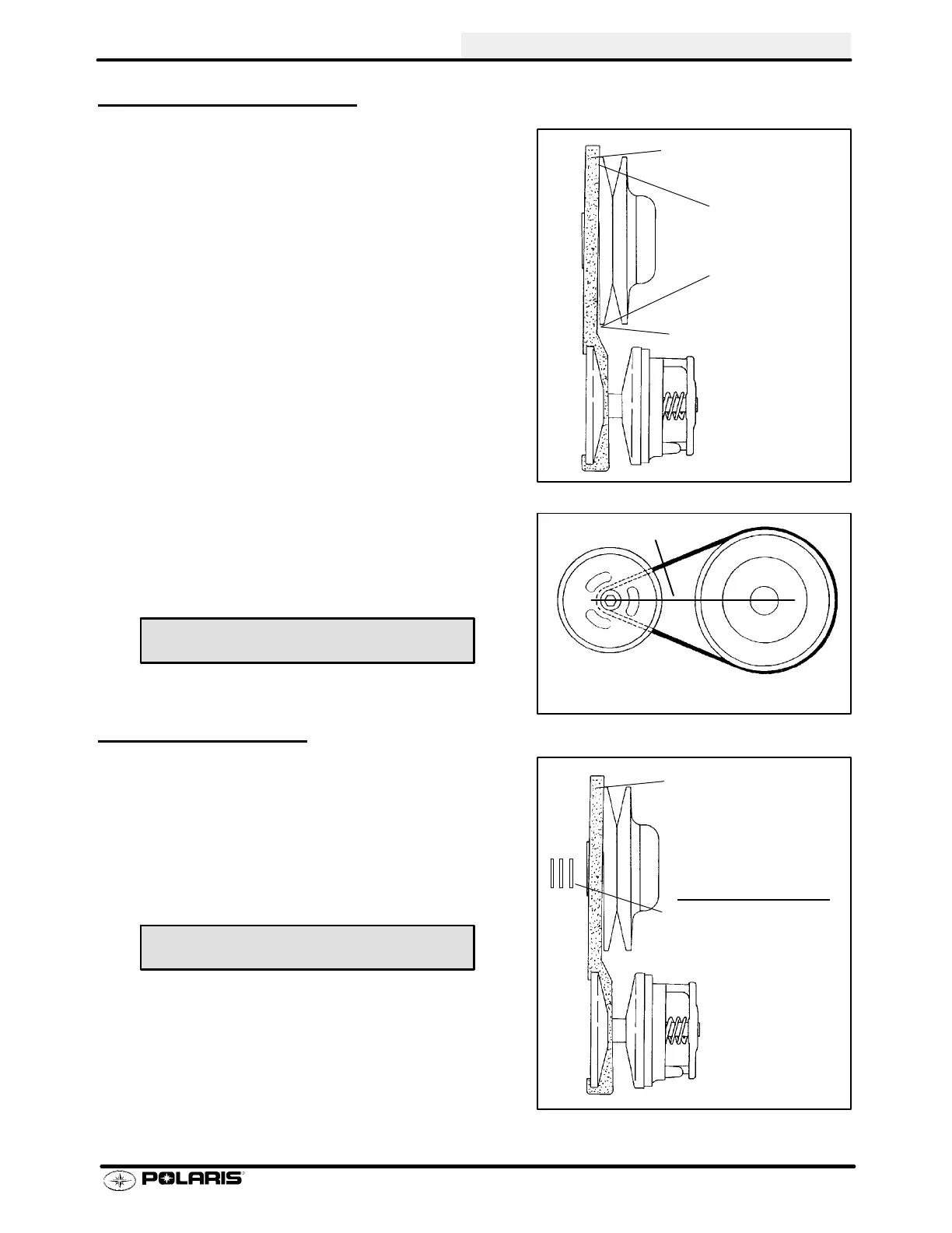
CLUTCH OFFSET
Important: Inspect clutch alignment and center distance be-
fore adjusting offset.
1. Install offset alignment tool as shown.
Offset is correct when rear of tool contacts rear of inner
sheave with driven clutch pushed completely inward on shaft
and bolt torqued. Adjust offset by adding or removing spacer
washers between back of drivenclutch andspacer asshown.
1/8I +0 / -- 1/16
3.2mm +0 / -- 1.6 mm)
Offset Alignment Tool
PN 2870654 - STD
PN 2872292 - EBS
B
A
Center line
Measure offset above and below
centerline
Shim Kit PN 2200126
Offset Alignment Tool
should contact rear edge
of driven clutch sheave
Driven Clutch Offset
To adjust, add or remove
washers from behind the
driven clutch
Spacer W asher PN 7556401

 Loading...