Quasar CP-3211/CP-4221 User and Installation Guide
12
5.3 Power and Ethernet Cable Connection
Power Connection
Make sure the camera’s power cable is properly connected. Refer to Tables 1 to 4: CP Series Camera
Connector Designations. If using Power over Ethernet (PoE Plus), make sure that Power Sourcing
Equipment (PSE) is available on the connected network. All electrical work must be performed in
accordance with local regulatory requirements.
Ethernet Cable Connection
Category 5 Ethernet cable is recommended for network connection. For best transmission quality,
cable length should not exceed 100 meters (328 feet). Connect one end of the Ethernet cable to the
RJ45 port on the Quasar HD PTZ camera and the other end to the network switch or PC.
See Figure 5: Indoor/Outdoor Connector Locations.
You can use an Ethernet crossover cable to connect the camera directly to a PC.
Check the status of the link indicator and activity indicator LEDs. If the LEDs are unlit, check the LAN
connection.
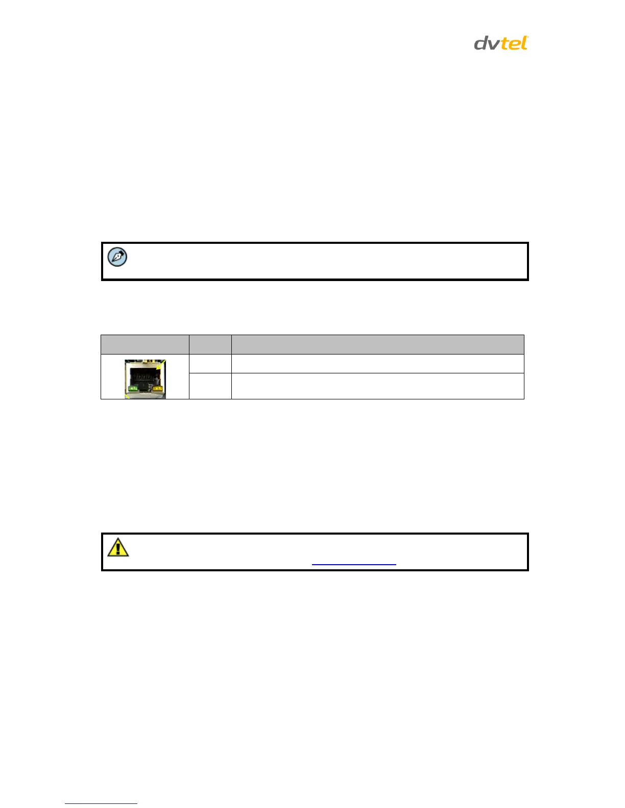
Table 6: RJ45 LED Description
Link light – Indicates a stable network connection
Activity light – flashes to indicate network activity
5.4 Initial Camera Configuration
To perform the initial camera configuration:
1. Unpack the camera. Rotate and remove the protective cover.
2. Remove the PE cloth sheet and lens cap. Attach the dome cover to the body.
3. On the camera back plate, plug the Cat 5 cable into the camera’s Ethernet port. If the network
does not use IEEE 802.3at PoE Plus, plug a properly rated 24VAC power supply into the
cameras’ power connector terminal block.
Caution:
Pay attention to the polarity noted in Camera Connectors.
 Loading...