Frequency Synthesizer
M30240 Group
Rev.1.00 Sep 24, 2003 Page 132 of 360
1.5.1.2 Set up of Frequency Synthesizer and DC-DC Converter
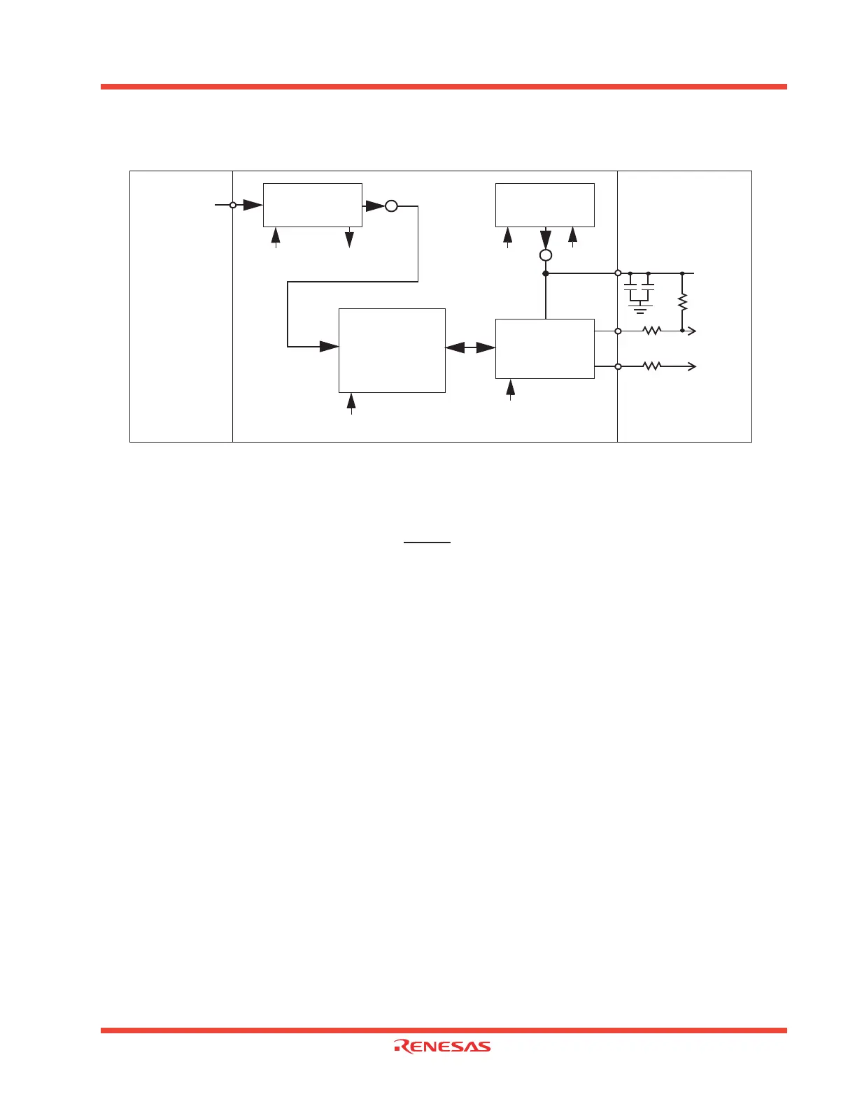
Figure 1.117: PLL, DC-DC Converter and USB Functional Block Diagram
A functional block diagram of the USB system on the M30240 which shows how the control signals
affect operation is given in Figure 1.117
1.5.1.3 Set up after Hardware Reset
A Hardware Reset occurs when either the RESET
pin is brought low for more than 2 µs or an invalid
opcode is fetched by the CPU. The frequency synthesizer (PLL) and DC-DC converter should be set
up as follows in the Hardware Reset routine (see Figure 1.118),
• Power up the M30240 and other components on the peripheral device for less than 100 mA opera-
tion. The current limit only applies for bus powered devices.
• Configure the PLL for 48MHz f(VCO) operation.
• Enable the PLL by setting FSE (bit 0 of the Frequency Synthesizer Control Register (FSC)) to a “1”,
then wait for 2 ms.
• Check the lock status bit (LS, bit 7 of FSC).
• If the bit is a “1”, go on.
• If the bit is a “0”, wait 0.1 ms longer and then re-check the bit.
• Enable the DC-DC converter in high current mode by setting USBC4 (bit 4 of the USB Control Reg-
ister (USBC)) to a “1” and keeping USBC3 (bit 3 of USBC) a “0”. High current mode should always
be used during normal USB operation. Low current mode should only be used during a USB sus-
pend.
• Wait (C + 1)ms (where C equals the external capacitance connected to the Ext Cap pin in µF) for
the voltage on Ext Cap to reach a steady state voltage of approximately 3.3V. (Since the D+ pullup
is connected to the Ext Cap pin, the upstream hub will detect that the peripheral device has been
plugged in once the voltage on D+ reaches approximately 2.0 V.)
•Example: A 2.2 µF capacitor connected to Ext Cap requires 3.2 ms for the voltage on Ext Cap to be stable.
• Enable the USB clock by setting USBC5 (bit 5 of USBC) to a “1”. (If the USB clock and FCU are
enabled before the voltage on Ext Cap is stable, a phantom USB Reset may be detected, or the ac-
tual USB Reset may not be detected.)
• Wait at least 4 cycles of Φ, then enable the USB FCU by setting USBC7 (bit 7 of USBC) to a “1”.
• Enable other blocks as necessary.
27-33
Ω
27-33
Ω
D+
D-
USB FCU
2.2
µ
F
0.1
µ
F
Ext Cap
Frequency
Synthesizer
f(Xin)
FSE LS
1.5 k
Ω
USB Transceiver
DC-DC Converter
USBC3
USBC4
USBC7
USBC7
USBC5
USBCLK
(48MHz)
enable lock
enable
enable
(enable)
(enable)
enable
current
mode
 Loading...


