Timer A
M30240 Group
Rev.1.00 Sep 24, 2003 Page 147 of 360
2.2.2 Operation
2.2.2.1 Timer mode
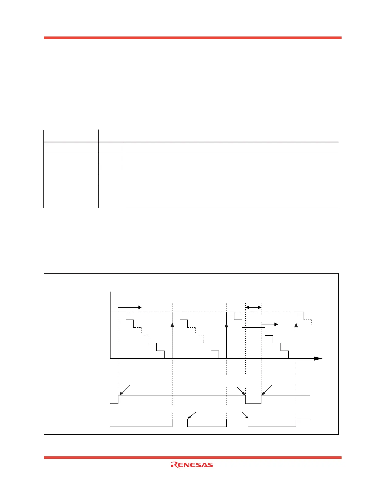
In timer mode, select functions from those listed in Table 2.1 . An example using the indicated options
is described below. Figure 2.7 shows the operation timing, and Figure 2.8 shows the set-up proce-
dure.
Table 2.1: Timer A timer mode functions
Operation
(1) Setting the count start flag to “1” causes the counter to perform a down count on the count source.
(2) If an underflow occurs, the content of the reload register is reloaded, and the count continues. At
this time, the Timer Ai interrupt request bit goes to “1”.
(3) Setting the count start flag to “0” causes the counter to hold its value and to stop
Figure 2.7: Timer mode timing operations
Item
Set-up
Count source O Internal count source (f1/f8/f32)
Pulse output function
O No pulses output
Pulses output
Gate function
O No gate function
Performs count only for the period when the TAiIN pin is at “L”.
Performs count only for the period when the TAiIN pin is at “H”.
FFFF16
n
0000
16
Time
Start count again
Count start flag
Timer Ai interrupt
request bit
“1”
“1”
Counter content (hex)
n = reload register content
Set to “1” by software
“0”
“0”
Set to “1” by software
Cleared to “0” by
software
Cleared to “0” when interrupt request is accepted, or cleared by software
(1) Start count (2) Underflow
(3) Stop count
 Loading...


