UART0 to UART2
M30240 Group
Rev.1.00 Sep 24, 2003 Page 78 of 360
1.2.23 UART0 to UART2
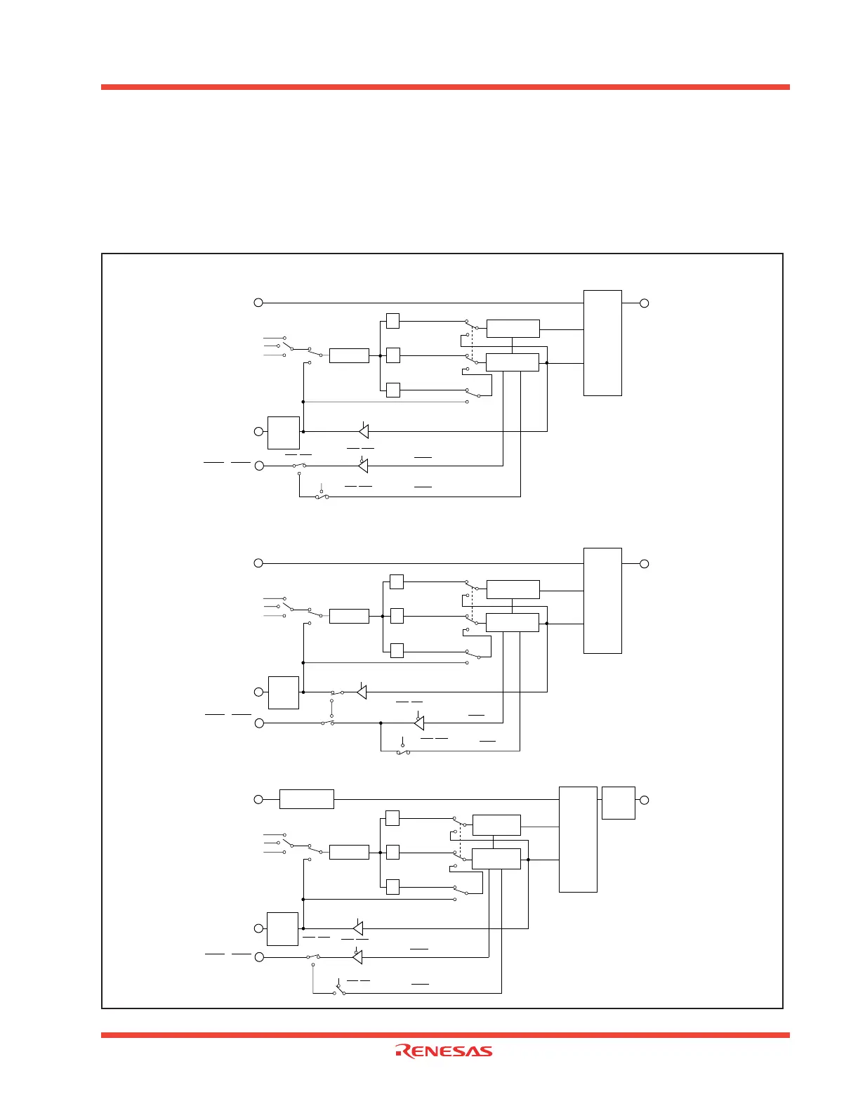
Serial I/O is configured as three channels: UART0, UART1, and UART2. UART0, UART1, and UART2
each have an exclusive timer to generate a transfer clock, so they operate independently of each other.
Figure 1.73 shows the block diagram of UART0, UART1, and UART2. Figure 1.74 and Figure 1.75 show
the block diagram of the transmit/receive unit.
Figure 1.73: Block diagram of UARTi (i=0 to 2)
n0 : Values set to UART0 bit rate generator (BRG0)
n1 : Values set to UART1 bit rate generator (BRG1)
n2 : Values set to UART2 bit rate generator (BRG2)
RxD2
Reception
control circuit
Transmission
control circuit
1 / (n
2
+1)
1/16
1/16
1/2
Bit rate generator
(address 0379
16
)
Clock synchronous type
(when internal clock is selected)
UART reception
Clock synchronous type
UART transmission
Clock synchronous type
Clock synchronous type
(when internal clock is selected)
Clock synchronous type
(when external clock is
selected)
Receive
clock
Transmit
clock
CLK2
CTS2 / RTS2
f
1
f
8
f
32
Vcc
RTS2
CTS2
TxD2
(UART2)
RxD polarity
reversing circuit
TxD
polarity
reversing
circuit
RxD0
1 / (n
0
+1)
1/2
Bit rate generator
(address 03A1
16
)
Clock synchronous type
(when internal clock is selected)
UART reception
Clock synchronous type
UART transmission
Clock synchronous type
Clock synchronous type
(when internal clock is selected)
Clock synchronous type
(when external clock is
selected)
Receive
clock
Transmit
clock
CLK0
Clock source selection
CTS0 / RTS0
f
1
f
8
f
32
Reception
control circuit
Transmission
control circuit
Internal
External
RTS0
CTS0
TxD0
Transmit/
receive
unit
RxD1
1 / (n
1
+1)
1/16
1/16
1/2
Bit rate generator
(address 03A9
16
)
Clock synchronous type
(when internal clock is selected)
UART reception
Clock synchronous type
UART transmission
Clock synchronous type
Clock synchronous type
(when internal clock is selected)
Clock synchronous type
(when external clock is
selected)
Receive
clock
Transmit
clock
CLK1
Clock source selection
f
1
f
8
f
32
Reception
control circuit
Transmission
control circuit
Internal
External
RTS1
CTS1
TxD1
(UART1)
(UART0)
CLK
polarity
reversing
circuit
CLK
polarity
reversing
circuit
CTS/RTS disabled
Clock output pin
select switch
CTS1 / RTS1
CLKS1
CTS/RTS disabled
CTS/RTS selected
CTS/RTS disabled
V
CC
CTS/RTS disabled
CTS/RTS disabled
CTS/RTS disabled
CTS/RTS
selected
CLK
polarity
reversing
circuit
Internal
External
Clock source selection
Transmit/
receive
unit
Transmit/
receive
unit
1/16
1/16
V
CC
 Loading...


