Timer A
M30240 Group
Rev.1.00 Sep 24, 2003 Page 73 of 360
1.2.21.3 One-shot timer mode
In this mode, the timer operates only once (See Table 1.21 ). When a trigger occurs, the timer starts
up and continues operating for a given period. Figure 1.66 shows the Timer Ai mode register in one-
shot mode.
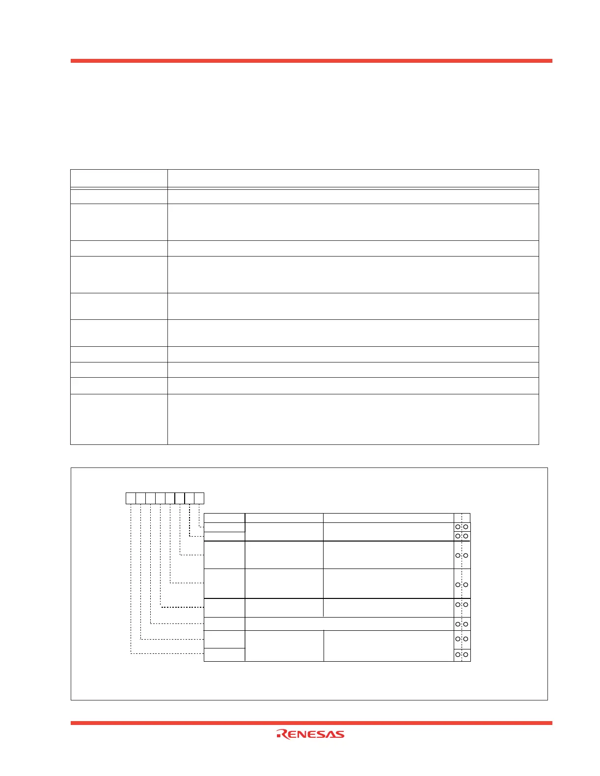
Figure 1.66: Timer Ai mode register in one-shot mode
Table 1.21: Timer specifications in one-shot timer mode
Item Specification
Count source f1, f8, f32
Count operation
•The timer counts down
•When the count reaches 0000
16, the timer stops counting after reloading a new count
• If a trigger occurs when counting, the timer reloads a new count and restarts counting
Divide ratio 1/n n: Set value
Count start condition
• An external trigger is input
• The selected timer overflows
• The one-shot start flag is set (= 1)
Count stop condition
• A new count is reloaded after the count has reached 0000
16
• The count start flag is reset (= 0)
Interrupt request
generation timing
The count reaches 000016
TAi
IN
pin function Programmable I/O port or trigger input
TAi
OUT
pin function Programmable I/O port or pulse output
Read from timer When timer Ai register is read, it indicates an indeterminate value
Write to timer
•When counting is stopped and a value is written to timer Ai register, it is written to both
reload register and counter
•When counting is in progress and a value is written to timer Ai register, it is written to the
reload register to be transferred to counter at next load time
Note 1: The settings of the corresponding port register and port direction register are invalid.
Note 2: Valid only when the TAi
IN
pin is selected by the event/trigger select bit.
(addresses 0382
16
and 0383
16
). If timer overflow is selected, this bit can be "1", or "0".
Note 3: Set the corresponding port direction register to “0”.
Timer Ai mode register
Symbol
Address
When reset
TAiMR(i=0 to 4)
0396
16
to 039A
16
00
16
Bit name FunctionBit symbol
b7 b6 b5 b4 b3 b2 b1 b0
Operation mode
select bit
1 0 : One-shot timer mode
b1 b0
TMOD1
TMOD0
MR0
Pulse output function
select bit
0 : Pulse is not output
(TA
iOUT
pin is a normal port pin)
1 : Pulse is output (Note 1)
(TA
iOUT
pin is a pulse output pin)
External trigger select bit
(Note 2)
0 : Falling edge of TAi
IN
pin's input signal
(Note 3)
1 : Rising edge of TAi
IN
pin's input signal
(Note
3)
MR2
MR1
MR3
0 (Must always be fixed to “0” in timer mode)
0 0 : f
1
0 1 : f
8
1 0 : f
32
1 1 : Reserved
b7 b6
TCK1
TCK0
Count source select bit
100
WR
Trigger select bit
0 : One-shot start flag is valid
1 : Selected by event/trigger select register
 Loading...


