Key-Input Interrupt
M30240 Group
Rev.1.00 Sep 24, 2003 Page 273 of 360
2.11.2 Operation
This section describes an example of the Key-input interrupt operation. Figure 2.121 shows an example
of a circuit that uses the key-input interrupt. Figure 2.122 shows an example of the timing operation for
the Key-input interrupt. Figure 2.123 shows the set-up procedure for the Key-input interrupt.
(1) Set the direction register of the ports to be changed to key-input interrupt pins to input, and set the
pull-up function.
(2) Setting the key-input interrupt control register and setting the interrupt enable flag makes the
interrupt-enabled state ready.
(3) If a falling edge is input to one of the pins KI0 to KI15, the Key-input interrupt request bit goes to “1”.
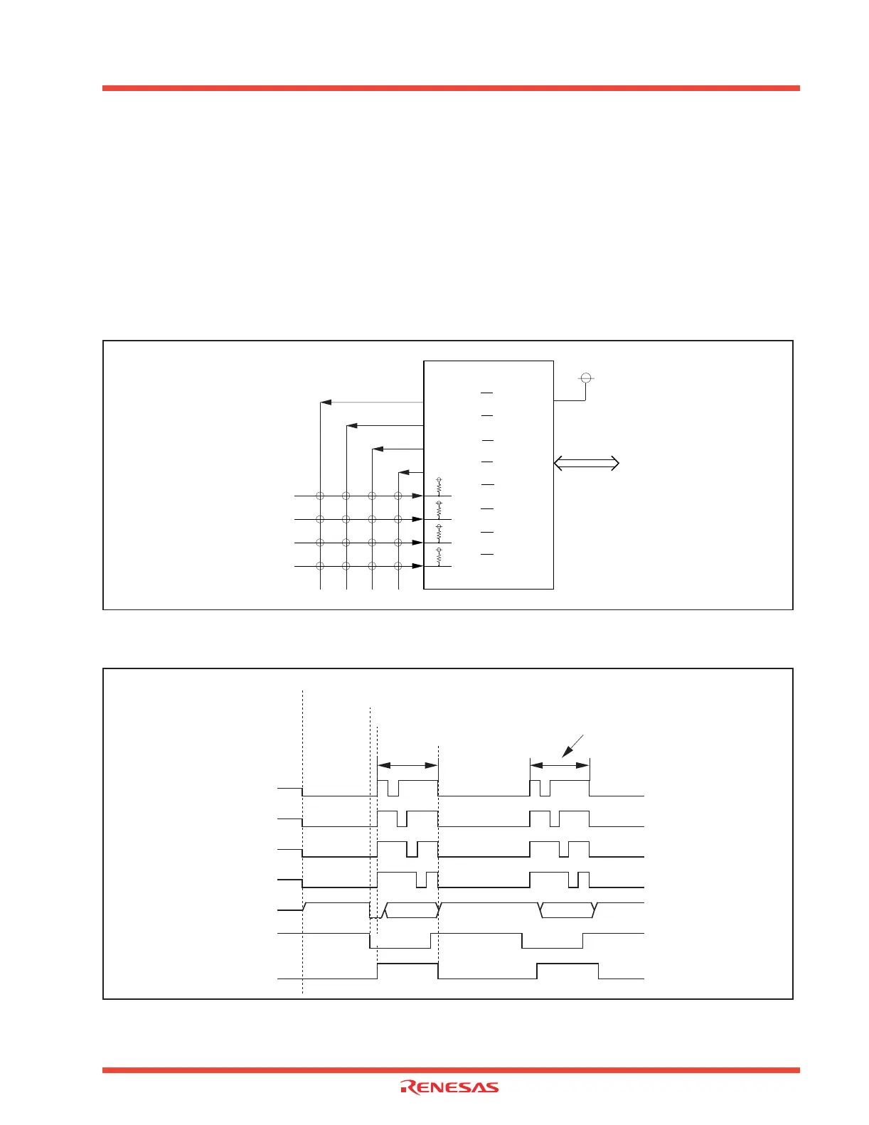
Figure 2.121: An example of the Key-input interrupt circuit
Figure 2.122: An example of the Key-input interrupt timing
P00 / KI0 V
REF
I/O port
P01 / KI1
P02 / KI2
P03 / KI3
P04 / KI4
P05 / KI5
P06 / KI6
P07 / KI7
P0
0
output
P0
1
output
P0
2
output
P0
3
output
P0
4
to P0
7
input
Key input
Key OFF Key OFF Key ON
Key input
interrupt processing
Key matrix scan
(1) Enter to stop mode
(2) Cancel stop mode
(3) Key scan
(4) Enter to stop mode
Key ON