Timer A
M30240 Group
Rev.1.00 Sep 24, 2003 Page 157 of 360
2.2.2.6 Two-phase Pulse Signal Process in Event Counter Mode with Normal Mode Selected
In processing 2-phase pulse signals in event counter mode, select functions from those listed in Table
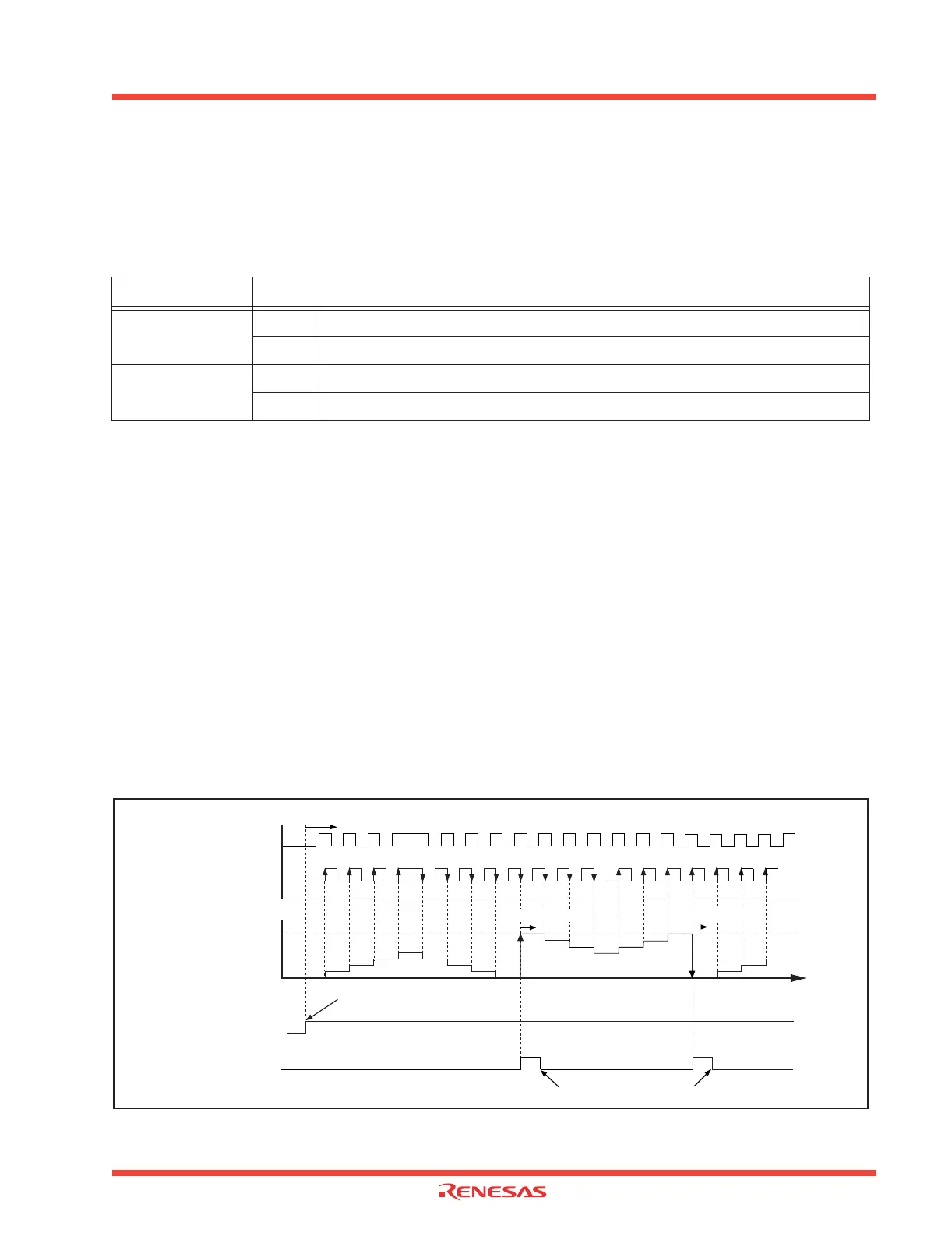
2.6 . An example using the indicated options is described below. Figure 2.17 shows the operation timing,
and Figure 2.18 shows the set-up procedure.
Table 2.6: Timer A Two-phase pulse signal process and event counter mode functions
Note: Only Timer A3 can select between normal and 4-multiplication processing.
Timer A2 is used only for normal processes.
Timer A4 is used only for 4-multiplication processes.
Operation
(1) Setting the count start flag to “1” causes the counter to count effective edges of the count source.
(2) Even if an underflow occurs, the content of the reload register is not reloaded, but the count con-
tinues. At this time, the Timer Ai interrupt request bit goes to “1”.
(3) Even if an overflow occurs, the content of the reload register is not reloaded, but the count contin-
ues. At this time, the Timer Ai interrupt request bit goes to “1”.
Note: The up count or down count conditions are as follows:
• If a rising edge is present at the TAiIN pin when the input signal level to the TAiOUT pin is “H”, an up
count is performed.
• If a falling edge is present at the TAiIN pin when the input signal level to the TAiOUT pin is “H”, a
down count is performed.
Figure 2.17: 2-phase pulse signal process in event counter mode timing operation
Item
Set-up
Count operation type
Reload type
O Free-run type
2-phase pulses
process (Note)
O Normal processing
4-multiplication processing
000016
Count start flag
Timer Ai interrupt
request bit
“1”
“0”
“1”
“0”
FFFF
16
Counter content (hex)
Input pulse
TA i OUT
“H”
“L”
“H”
“L”
TA i
IN
Set to “1” by software
Cleared to “0” when interrupt request is accepted, or cleared by software
(1) Start count
(2) Underflow
(3) Overflow
Time