Universal Serial Bus
M30240 Group
Rev.1.00 Sep 24, 2003 Page 320 of 360
3.2.11 USB Receive (OUT)
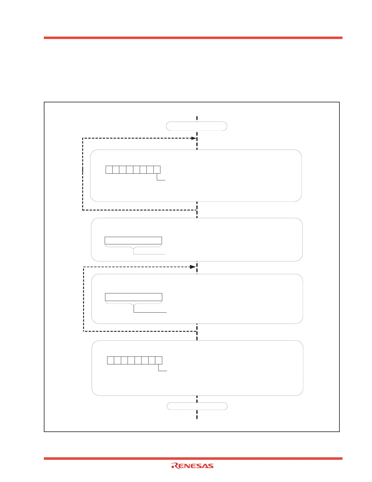
The procedures for Endpoint 1-4 USB OUT transmission are shown in Figure 3.33 If isochronous
transfer is used, it is necessary to be aware that a USB Endpoint x OUT interrupt occurs even when
OVER_RUN is “1.
Figure 3.33: Procedures for receiving USB Transmission
USB Endpoint x OUT Write Count Register Address
EPiWC (i = 1-4) 031D
16, 032516,
032D16, 033516
Read Data Count
b7
b0
Reading Data Count
USB Endpoint x OUT Interrupt Processing Routine
Confirm Data Reception in FIFO
USB Endpoint x OUT Control and Status Register Address
EPiOCS (i = 1-4) 031A
16, 032216,
032A16, 033216
OUT_PKT_RDY Bit (Note)
0 : Not ready
1 : Data packet ready
b7 b0
Register Refuge Process
Note: Wait until bit becomes "1".
Register Recover Processing
REIT Command Implementation
USB Endpoint x FIFO Register Address
EPi (i = 1-4) 0339
16, 033A16,
033B
16, 033C16
b7
b0
Read Data from FIFO
Clearing OUT_PKT_RDY Flag
USB Endpoint x OUT Control and Status Register Address
EPiOCS (i = 1-4) 031A
16, 032216,
032A16, 033216
OUT_PKT_RDY Bit (Note)
0 : Data packet read complete
b7 b0
Note: In the event the AUTO_CLR bit is "1", it automatically becomes "0". In the event of a double buffer zone, the
OUT_PKT_RDY flag remains "1" even after 1 packet data has been read because data remains in the OUT FIFO. In this
case, the OUT_PKT_RDY cannot be cleared to "0".
Note: Read the data count that is equal to the amount of received data.
0
Unload Received Data
1
 Loading...


