Timer A
M30240 Group
Rev.1.00 Sep 24, 2003 Page 167 of 360
2.2.2.11 Pulse width modulation mode - 8-bit PWM mode selected
In pulse width modulation mode, select functions from those listed in Table 2.12 . An example using the
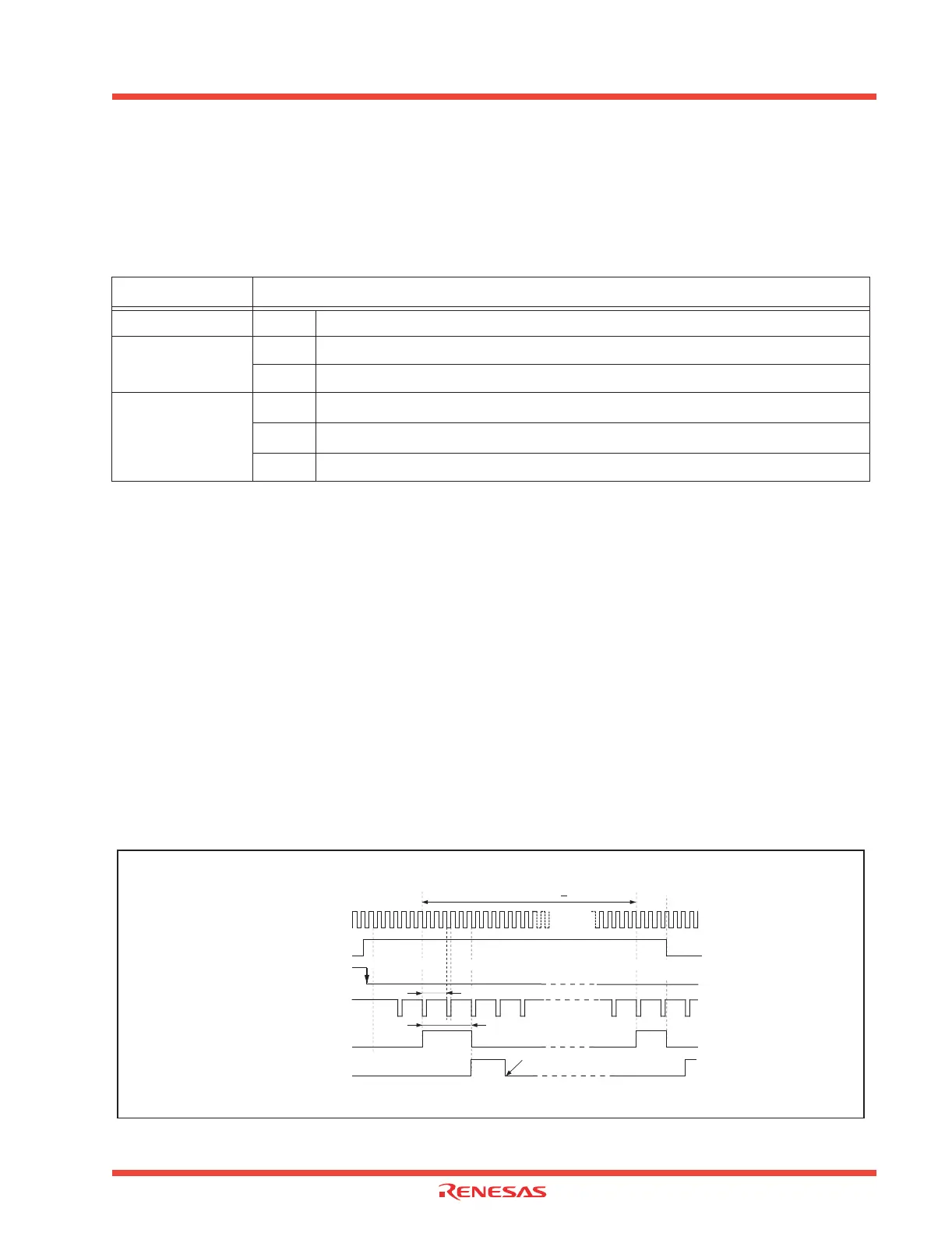
indicated options is described below. Figure 2.27 shows the operation timing, and Figure 2.28 shows
the set-up procedure.
Table 2.12: Timer A pulse width modulation mode 8-bit PWM mode selected
Note: j = i - 1, but j = 4 when i = 0; k = i + 1 when i = 4
Operation
(1) If the TAi
IN
pin input level changes from “H” to “L” with the count start flag set to “1”, the counter
performs a down count on the count source. Also, the TAi
OUT
pin outputs an “H” level.
(2) The TAi
OUT
pin output level changes from “H” to “L” when a set time period elapses. At this time,
the Timer Ai interrupt request bit goes to “1”.
(3) The counter reloads the content of the reload register every time PWM pulses are output for one
cycle, and continues counting.
(4) Setting the count start flag to “0” causes the counter to hold its value and to stop. Also, the TAi
OUT
pin outputs an “L” level.
Notes
• The period of PWM pulses becomes (m + 1) X (2
8
– 1) / fi, and the “H” level pulse width becomes n
X (m + 1) / fi. If “00
16
” is set in the eight higher-order bits of the Timer Ai register, the pulse width
modulator does not work, and the TAi
OUT
pin output level remains at “L”.
(fi: frequency of the count source f1, f8, f32; n: value of the timer)
• When a trigger is generated, the TAiout pin outputs “L” level of same amplitude as “H” level of the
set PWM pulse, after which it starts PWM pulse output.
Figure 2.27: Operation timing of pulse width modulation mode, with 8-bit PWM mode selected
Item
Set-up
Count source O Internal count source (f1/f8/f32)
PWM mode
16-bit PWM
O 8-bit PWM
Count start condition
O
External trigger input (falling edge of input signal to the TAi
IN
pin)
External trigger input (rising edge of input signal to the TAi
IN
pin)
Timer overflow (TB2/TAj/TAk overflow)
Count source (Note 1)
Reload register high-order 8 bits = 02
16
Reload register low-order 8 bits = 0216
External trigger (falling edge of TAi IN pin input signal) is selected
1 / f
i
X (m
+ 1) X (2 1)
8
TA iIN pin input
Underflow signal of 8-bit
prescaler (Note 2)
PWM pulse output from
TA
iOUT pin
"H"
"H"
"L"
"L"
Timer Ai interrupt
request bit
"H"
"L"
"1"
"0"
Note 1: The 8-bit prescaler counts the count source.
Note 2: The 8-bit pulse width modulator counts the 8-bit prescaler's underflow signal.
Note 3: m = 00
16 to FE16; n = 0016 to FE16.
1 / f
i
X (m + 1) X n
Count start flag
"1"
"0"
(1) Start count
(2) Output level "H" to "L"
Cleared to "0" when interrupt request
is accepted, or cleared by software
(3)
(4) Stop count
1 / f
i
X (m+1)
Conditions:
One period is
complete
 Loading...


