Attach/Detach Function
M30240 Group
Rev.1.00 Sep 24, 2003 Page 135 of 360
1.5.2 Attach/Detach Function
The Attach/Detach Function can be used to attach or detach a USB function from the host without
disconnecting the cable. When attaching a USB function, the connect registers should be set to 03
16
at
the same time on or before the DC-DC Converter is enabled. Similarly, when detaching the connect
register, it should be set to 01
16
when powering down the DC-DC Converter.
If you do not set the connect (address 001F
16
) to HIGH, the system will default to its normal mode.
Note: If the D+ is connected to EXTCAP, this mode will not work.
D+ is connected to EXTCAP through a 1.5 K resistor in compliance with the USB specification. USB
Suspend/Resume Function
Hardware connections are shown below
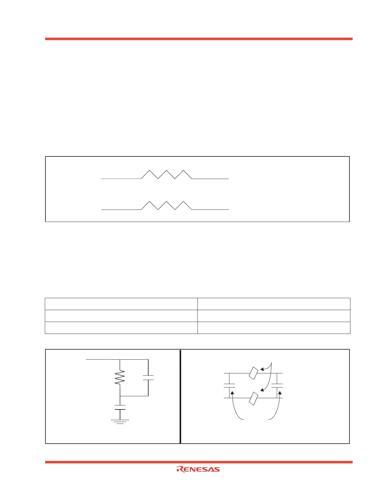
1.5.3 Low Pass Filter Network
All passive components should be in close proximity to pin 78 (LPF), capacitors should be X7R di-
electric or better. The recommended values are listed in Table 1.51. See Figure 1.119 for schematic of
the LPF.
Analog V
ss
and Analog V
cc
, pins 77 and 80 should have isolated connections to the digital V
ss
and V
cc
ground planes. Figure 1.120 shows the power supply isolation.
Table 1.51: Recommended values
Figure 1.119: LPF Filter Schematic Figure 1.120: Power Supply
R = 1000
Ω
10%
C2 = 680 pf 10%
C1 = 0.1 µf 10%
Attach is connected to D+ through 1.5 K resistor.
ATTACH [P8
3
]
D+ (pin 9 M30240)
Attach/Detach mode disabled
EXTCAP D+ (pin 9 M30240)
1.5 K
1.5 K
R
C1
C2
Pin 78
(LPF)
Pin 77
AVss
Digital
Vcc
(on card)
Digital
Vss
Analog
Vss (Pin
77)
Analog
Vcc
(Pin 80)
C
C
Decoupling
Capacitors
Ferrite Beads
Figure 1.119
Figure 1.120
 Loading...


