Timer A
M30240 Group
Rev.1.00 Sep 24, 2003 Page 74 of 360
1.2.21.4 Pulse-width modulation (PWM) mode
In this mode, the timer outputs pulses of a given width in succession (See Table 1.22 ). In this mode,
the counter functions as either a 16-bit pulse-width modulator or an 8-bit pulse-width modulator. Figure
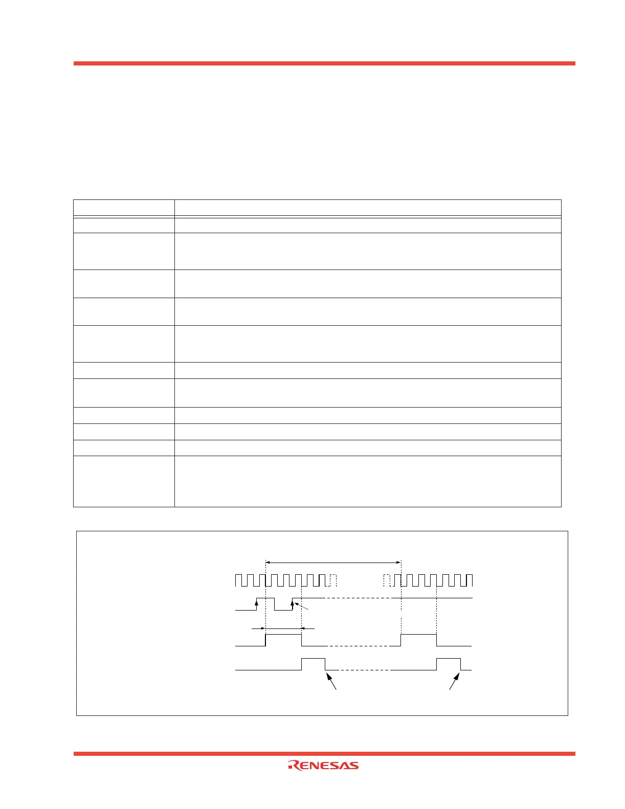
1.67 shows an example of how a 16-bit pulse-width modulator operates. Figure 1.68 shows the Timer
Ai mode register in pulse-width modulation mode. Figure 1.69 shows the example of how an 8-bit
pulse width modulator operates.
Figure 1.67: Example of how a 16-bit pulse-width modulator operates
Table 1.22: Timer specifications in pulse-width modulation mode
Item Specification
Count source f1, f8, f32
Count operation
•The timer counts down (operating as an 8-bit or a 16-bit pulse-width modulator)
•The timer reloads a new count at a rising edge of PWM pulse and continues counting
• The timer is not affected by a trigger that occurs when counting
16-bit PWM
•High level width n / f
i
n: Set value
•Cycle time (2
16
-1) / f
i
fixed
8-bit PWM
•High level width n (m+1) /f
i
n: values set to timer Ai register’s high-order address
•Cycle time (2
8
-1) (m+1) /f
i
m: values set to timer Ai register’s low-order address
Count start condition
•External trigger is input
•The timer overflows
•The count start flag is set (= 1)
Count stop condition •The count start flag is reset (= 0)
Interrupt request
generation timing
PWM pulse goes “L”
TAi
IN
pin function Programmable I/O port or trigger input
TAi
OUT
pin function Pulse output
Read from timer When Timer Ai register is read, it indicates an indeterminate value
Write to timer
•When counting is stopped and a value is written to Timer Ai register, it is written to both
reload register and the counter
•When counting in progress and a value is written to Timer A register, it is written to only
reload register to be transferred to the counter at next reload timer.
1 / f
i
X
(2 – 1)
16
Count source
TA
i
IN
pin
input signal
PWM pulse output
from TA
iOUT
pin
Condition : Reload register = 0003
16
, when external trigger
(rising
edge of TA iIN
pin input signal) is selected
Trigger is not generated by this signal
“H”
“H”
“L”
“L”
Timer Ai interrupt
request bit
“1”
“0”
Cleared to “0” when interrupt request is accepted, or cleared by software
f
i
: Frequency of count source
(f
1
, f
8
, f
32
)
16
to FFFE
16
1 / f
i
X
n
Note: n = 0000