Timer A
M30240 Group
Rev.1.00 Sep 24, 2003 Page 75 of 360
Figure 1.68: Timer Ai mode register in pulse-width modulation mode
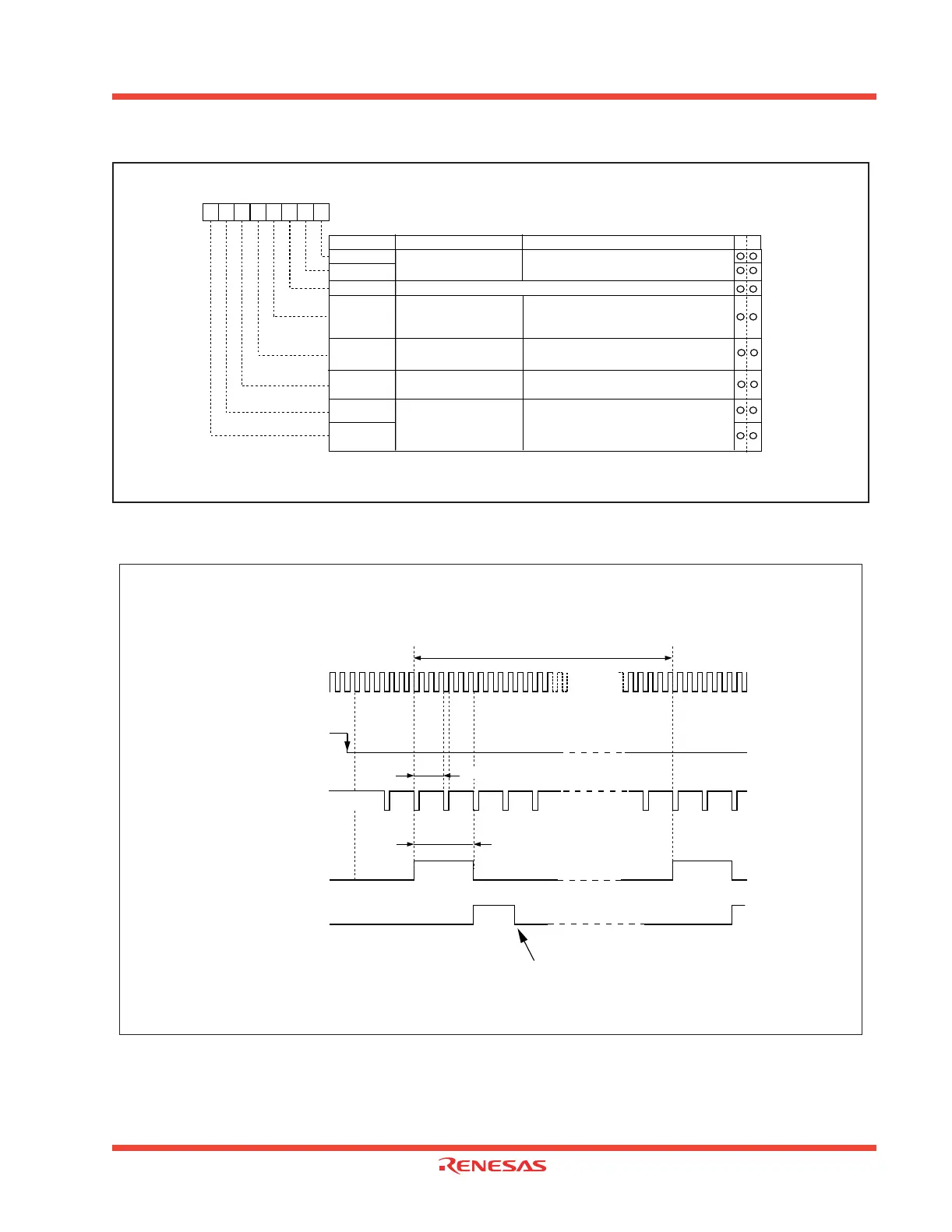
Figure 1.69: Example of how an 8-bit pulse-width modulator operates
Note 1: Valid only when the TAi
IN
pin is selected by the event/trigger select bit.
(addresses 0382
16
and 0383
16
). If timer overflow is selected, this bit can be "1", or "0".
Note 2: Set the corresponding port direction register to “0”.
Timer Ai mode register
Symbol
Address
When reset
TAiMR(i=0 to 4)
0396
16 to 039A16
0016
Bit name FunctionBit symbol
b7 b6 b5 b4 b3 b2 b1 b0
Operation mode
select bit
1 1 : PWM mode
b1 b0
TMOD1
TMOD0
MR0
External trigger select bit
(Note 1)
0 : Falling edge of TAi
IN pin's input signal
(Note 2)
1 : Rising edge of TAi
IN pin's input signal
(Note 2)
MR2
MR1
MR3
Must always be "1" in PWM mode)
0 0 : f
1
0 1 : f8
1 0 : f
32
1 1 : Reserved
b7 b6
TCK1
TCK0
Count source select bit
111
WR
Trigger select bit
0 : Functions as a 16-bit pulse width modulator
1 : Functions as an 8-bit pulse width modulator
16/8 PWM mode select bit
0 : Count start flag is valid
1 : Selected by event /trigger select register
Count source (Note1)
TA
iIN
pin input signal
Underflow signal of
8-bit prescaler (Note 2)
PWM pulse output
from TA
iOUT
pin
“H”
“H”
“H”
“L”
“L”
“L”
“1”
“0”
Timer Ai interrupt
request bit
Cleared to “0” when interrupt request is accepted, or cleared by software
f
i
: Frequency of count source
(f
1
, f
8
, f
32
)
Note 1: The 8-bit prescaler counts the count source.
Note 2: The 8-bit pulse width modulator counts the 8-bit prescaler's underflow signal.
Condition : Reload register high-order 8 bits = 0216
Reload register low-order 8 bits = 0216
External trigger (falling edge of TAiIN pin input signal) is selected
1 / f
i
X (m
+ 1) X (2 – 1)
8
1 / f
i
X (m + 1) X n
1 / f
i
X (m + 1)
Note 3: m = 00
16
to FE
16
; n = 00
16
to FE
16