Clock-Asynchronous Serial I/O
M30240 Group
Rev.1.00 Sep 24, 2003 Page 210 of 360
2.5.2 Operation
2.5.2.1 Transmission in UART mode
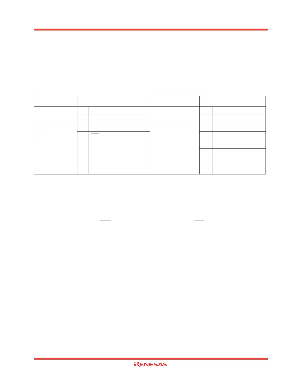
For transmitting data in UART mode, select functions from those listed in Table 2.20 . An example using
the indicated options is described below. Figure 2.62 shows the operation timing, and Figure 2.63 and
Figure 2.64 show the set-up procedures.
Table 2.20: Serial I/O transmission in UART mode functions
Note 1: UART0, UART1 only.
Note 2: UART2 only.
Operation
(1) Setting the transmit enable bit to “1” and writing transmission data to the UARTi transmit buffer reg-
ister readies the data transmissible status.
(2) When the input to the CTSi
pin goes to “L”, transmission starts (the CTSi pin needs to be controlled
on the reception side).
(3) Transmission data held in the UARTi transmit buffer register is transmitted to the UARTi transmit
register. At this time, the first bit (the start bit) of the transmission data is transmitted from the TxDi pin.
Then, data is transmitted, bit by bit, in sequence: LSB, ····, MSB, parity bit, and stop bit(s).
(4) When the stop bit(s) is (are) transmitted, the transmit register empty flag goes to “1”, which indi-
cates that transmission is completed. At this time, the UARTi transmit interrupt request bit goes to “1”.
The transfer clock stops at “H” level.
(5) If the transmission condition of the next data is ready when transmission is completed, a start bit
is generated following the stop bit(s), and the next data is transmitted.
Item
Set-up Item Set-up
Transfer clock source
O Internal clock (f1/f8/f32)
Sleep mode (Note 1)
O Sleep mode off
External clock (CLKi pin) Sleep mode on
CTS
function
O CTS
function enabled
Data logic select function
(Note 2)
O No reverse
CTS
function disabled Reverse
Transmission
interrupt factor
Transmission buffer empty
TxD, RxD I/O polarity
reverse bit (Note 2)
O No reverse
Reverse
O Transmission comlpete
Bus collision detection
function (Note 2)
O Not selected
Selected
 Loading...


