Address Match Interrupt
M30240 Group
Rev.1.00 Sep 24, 2003 Page 36 of 360
1.2.15 Address Match Interrupt
An address match interrupt is generated when the address match interrupt address register contents
match the program counter value. Two address match interrupts can be set, each of which can be
enabled and disabled by an address match interrupt enable bit. Address match interrupts are not
affected by the interrupt enable flag (I flag) and processor interrupt priority level (IPL).
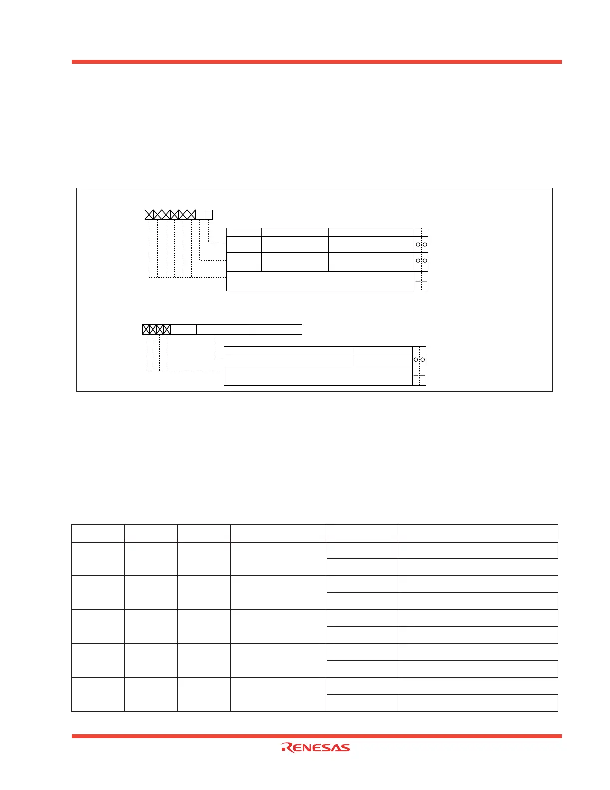
Figure 1.20 shows the address match interrupt-related registers.
Figure 1.20: Address match interrupt-related registers
1.2.16 Watchdog Timer
The watchdog timer has the function of detecting when the program is out of control. The watchdog timer
is a 15-bit counter that decrements using the clock derived by dividing the internal clock Φ using the
prescaler. A watchdog timer interrupt is generated when an underflow occurs in the watchdog timer. Bit
7 of the watchdog timer control register (address 000F
16
) selects the prescaler division ratio (by 16 or
128). Table 1.13 shows the periodic table for the watchdog timer.
Table 1.13: Watchdog timer periodic table (f(X
IN)=12MHz)
Note: The watchdog timer’s period is subject to some error due to the prescaler.
CM06 CM17 CM16 Internal clock Φ WDC7 Period (Note)
000 12MHz
0 Approx. 43.7ms
1 Approx. 349.5ms
001 6MHz
0 Approx. 87.4ms
1 Approx. 699.1ms
010 3MHz
0 Approx. 174.8ms
1 Approx. 1.40s
0 1 1 0.75MHz
0 Approx. 699.1ms
1 Approx. 5.59s
1 Invalid Invalid 1.5MHz
0 Approx. 349.5ms
1 Approx. 2.80s
Bit nameBit symbol
Symbol Address When reset
AIER 0009
16
XXXXXX00
2
Address match interrupt enable register
Function
WR
Address match interrupt 0
enable bit
0 : Interrupt disabled
1 : Interrupt enabled
AIER0
Address match interrupt 1
enable bit
AIER1
Symbol Address When reset
RMAD0 0012
16
to 0010
16
X00000
16
RMAD1 0016
16
to 0014
16
X00000
16
Nothing is assigned.
b7 b6 b5 b4 b3 b2 b1 b0
WR
Address setting register for address match interrupt
Function Values that can be set
Address match interrupt register i (i = 0, 1)
00000
16
to FFFFF
16
Nothing is assigned.
0 : Interrupt disabled
1
:
Interrupt
enabled
b0 b7 b0b3
(b19) (b16)
b7 b0
(b15) (b8)
b7
(b23)
Write 0 when writing to these bits. If read, the value is indeterminate.
Write 0 when writing to these bits. If read, the value is indeterminate.
 Loading...


