Watchdog Timer
M30240 Group
Rev.1.00 Sep 24, 2003 Page 267 of 360
2.9.2 Operation
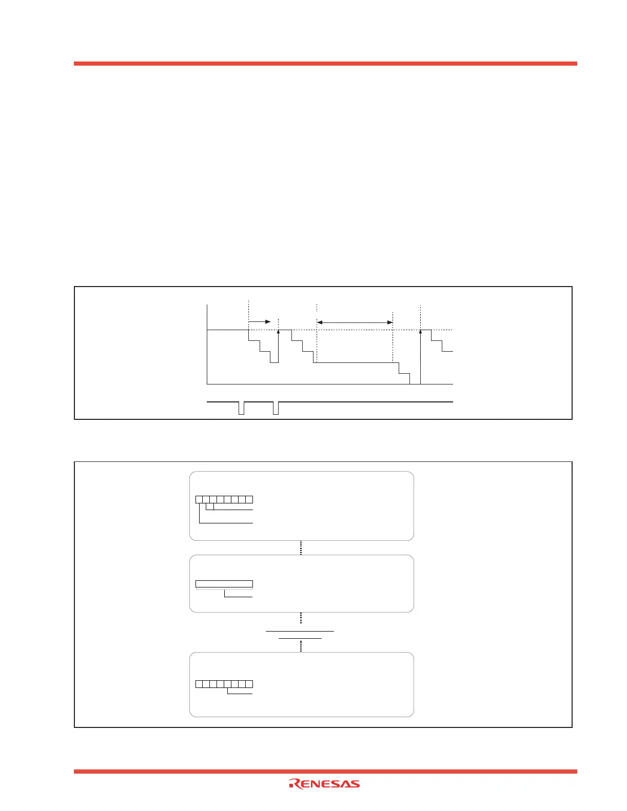
The following describes the operation of the Watchdog timer. Figure 2.112 shows the operation timing,
and Figure 2.113 shows the set-up procedure.
(1) Writing to the Watchdog timer start register initializes the Watchdog timer to 7FFF
16
and causes it to
start a down count.
(2) With a count in progress, writing to the Watchdog timer start register again initializes the Watchdog
timer to 7FFF
16
and causes it to resume counting.
(3) Either executing the WAIT instruction or going to the stopped state causes the Watchdog timer to
hold the count in progress and to stop counting. The Watchdog timer resumes counting after returning
from the execution of the WAIT instruction or from the stopped state.
(5) If the Watchdog timer underflows, it is initialized to 7FFF
16
and continues counting. At this time, a
Watchdog timer interrupt occurs.
Figure 2.112: Operation timing of Watchdog timer
Figure 2.113: Set-up procedure of Watchdog timer
(1) Start count
Write signal to the
watchdog timer
start register
7FFF
16
000016
“H”
“L”
(4) Generate
watchdog timer
interrupt
(2) Write operation
(3)
In stopped state, or WAIT
instruction is executing, etc
Reserved bit
Must always be “0”
Watchdog timer control register [Address 000F
16]
WDC
Setting watchdog timer control register
b7 b0
Setting watchdog timer start register
The watchdog timer is initialized and starts counting with a write instruction to
this register. The watchdog timer value is always initialized to “7FFF
16”
regardless of the value written.
Watchdog timer start register [Address 000E
16]
WDTS
b0b7
Software reset
Software reset bit
The device is reset when this bit is set to “1”. The value of this bit
is “0” when read.
Processor mode register 0 [Address 0004 16]
PM0
b7 b0
1
Generating watchdog
timer interrupt
00
Prescaler select bit
0 : Divided by 16
1 : Divided by 128