Timer A
M30240 Group
Rev.1.00 Sep 24, 2003 Page 145 of 360
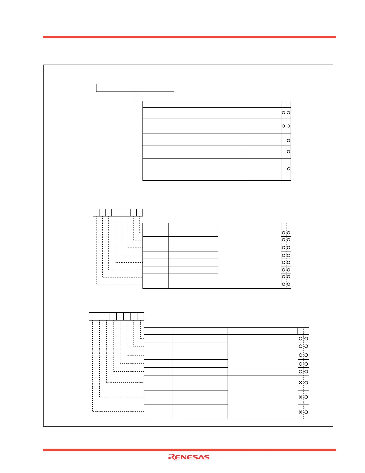
Figure 2.5: Timer A related register (2)
Symbol Address When reset
TABSR 0380
16 0016
Count start flag
Bit name
Bit symbol
WR
b7 b6 b5 b4 b3 b2 b1 b0
Timer B2 count start flag
Timer B1 count start flag
Timer B0 count start flag
Timer A4 count start flag
Timer A3 count start flag
Timer A2 count start flag
Timer A1 count start flag
Timer A0 count start flag
0 : Stops counting
1 : Starts counting
TB2S
TB1S
TB0S
TA4S
TA3S
TA2S
TA1S
TA0S
Function
Symbol Address When reset
TA0 0387
16, 038616 Indeterminate
TA1 0389
16, 038816 Indeterminate
TA2 038B
16, 038A16 Indeterminate
TA3 038D
16, 038C16 Indeterminate
TA4 038F
16, 038E16 Indeterminate
b7 b0 b7 b0
(b15) (b8)
Timer Ai register (Note)
WR
• Timer mode 000016 to FFFF16
Counts an internal count source
• Event counter mode 0000
16 to FFFF16
Counts pulses from an external source or timer overflow
• One-shot timer mode 0000
16 to FFFF16
Counts a one-shot width
• Pulse-width modulation mode (16-bit PWM) 0000
16 to FFFF16
Functions as a 16-bit pulse width modulator
• Pulse width modulation mode (8-bit PWM) 00
16 to FE16
Timer low-order address functions as an 8-bit (Both high-order
prescaler and high-order address functions as an 8-bit and low-order
pulse-width modulator addresses)
Function
Values that can be set
Note: Read and write
data in 16-bit units.
X
X
X
Timer A4 up/down flag
Timer A3 up/down flag
Timer A2 up/down flag
Timer A1 up/down flag
Timer A0 up/down flag
Timer A2 two-phase pulse
signal processing select bit
Timer A3 two-phase pulse
signal processing select bit
Timer A4 two-phase pulse
signal processing select bit
Symbol Address When reset
UDF 0384
16 0016
TA4P
TA3P
TA2P
Up/down flag
Bit name FunctionBit symbol
WR
b7 b6 b5 b4 b3 b2 b1 b0
TA4UD
TA3UD
TA2UD
TA1UD
TA0UD
0 : Down count
1 : Up count
This specification becomes valid
when the up/down flag content is
selected for up/down switching
cause
0 : two-phase pulse signal
processing disabled
1 : two-phase pulse signal
processing enabled
When not using the two-phase
pulse signal processing function,
set the select bit to “0”
 Loading...


