Timer A
M30240 Group
Rev.1.00 Sep 24, 2003 Page 150 of 360
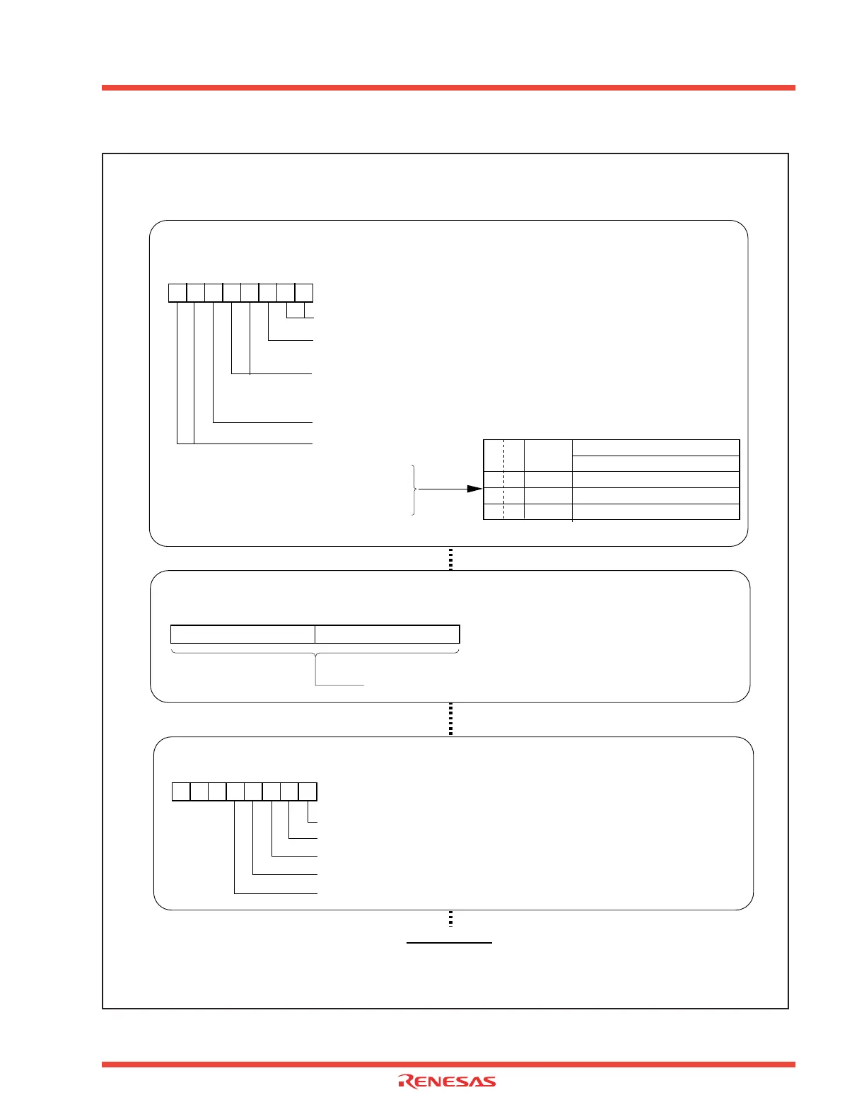
Figure 2.10: Set-up procedure for timer mode and gate function
Setting divide ratio
Can be set to 000016 to FFFF16
b7 b0
(b15) (b8)
b7 b0
Timer A0 register [Address 0387 16, 038616] TA0
Timer A1 register [Address 0389
16, 038816] TA1
Timer A2 register [Address 038B
16, 038A16] TA2
Timer A3 register [Address 038D
16, 038C16] TA3
Timer A4 register [Address 038F
16, 038E16] TA4
Pulse output function select bit
0 : Pulse is not output (TA
iOUT pin is a normal port pin)
Selecting timer mode and functions
Timer Ai mode register (i=0 to 4) [Address 0396 16 to 039A16]
TAiMR (i=0 to 4)
Gate function select bit
1 1 : Timer counts only when TA
iIN pin is held “H” (Note)
b4 b3
Selection of timer mode
b7 b0
0000
0 (Must always be “0” in timer mode)
Count source select bit
0 0 : f
1
0 1 : f 8
1 0 : f 32
1 1 : Reserved
b7 b6
Note: Set the corresponding port direction register to “0”.
11
Count source period
f(XIN) : 12MH Z
b7 b6
Count
source
83.3ns
667ns
2.67.µs
00
01
10
f1
f8
f32
Setting count start flag
Count start flag [Address 0380 16]
TABSR
Timer A0 count start flag
Timer A1 count start flag
Timer A2 count start flag
Timer A3 count start flag
Timer A4 count start flag
b7 b0
Start count
 Loading...


