Universal Serial Bus
M30240 Group
Rev.1.00 Sep 24, 2003 Page 316 of 360
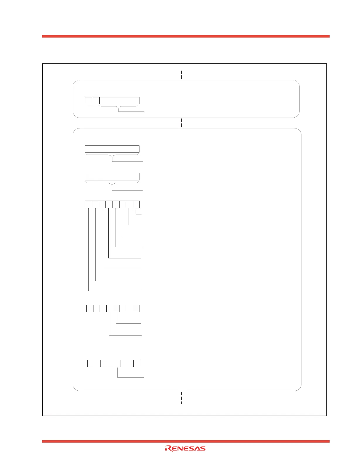
Figure 3.29: Initializing USB Function Control Unit (3)
Endpoint 0 Control Transfer
USB Endpoint 0 MAXP Register Address
EP0MP 031316
00
16
to 3F
16
Endpoint 1 - 4 (Bulk, Interrupt, and Isochronous transfers) Initialization
USB Endpoint x IN MAXP Address
EPiIMP (i = 1-4) 031B
16, 032316, 032B16, 033316
00
16
to FF
16
possible
USB Endpoint x OUT MAXP Address
EPiOMP (i = 1-4) 031C
16, 032416, 032C16, 033416
00
16
to FF
16
possible
USB Endpoint Enable Register Address
USBEPEN 030B
16
Endpoint 1 OUT FIFO Enable bit
0 : Disabled
1 : Enabled
Endpoint 1 IN FIFO Enable bit
0 : Disabled
1 : Enabled
Endpoint 2 OUT FIFO Enable bit
0 : Disabled
1 : Enabled
Endpoint 2 IN FIFO Enable bit
0 : Disabled
1 : Enabled
Endpoint 3 OUT FIFO Enable bit
0 : Disabled
1 : Enabled
Endpoint 3 IN FIFO Enable bit
0 : Disabled
1 : Enabled
Endpoint 4 OUT FIFO Enable bit
0 : Disabled
1 : Enabled
Endpoint 4 IN FIFO Enable bit
0 : Disabled
1 : Enabled
USB Endpoint x IN Control and Status Register Address
EPiICS (i = 1-4) 0319
16, 032116, 032916, 033116
ISO Bit
0 : Exclude
1 : Initialize to isochronous transfer endpoint
INTPT Bit (Note)
0 : Exclude
1 : Initialize to interrupt transfer endpoint (rate feedback)
Continued on next page
b7
b0
0
0
b7
b7
b0
b0
b7
b0
Note: "0" should be set if standard interrupt transfer is used.
USB Endpoint x OUT Control and Status Register Address
EPiOCS (i = 1-4) 031A
16, 032216, 032A16, 033216
ISO Bit
0 : Exclude
1 : Initialize to isochronous transfer endpoint
Continued from previous page
b0
b7
b7
b0
 Loading...


