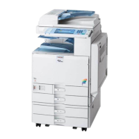
Technical Bulletin PAGE: 1/3
Subject: Parts Information for tandem tray end fence
Prepared by: Takeshi Toriumi
From: 1st Tech Service Sect. MFP/P Tech Service Dept.
Mechanical
Paper path
Product Safety
Electrical
Transmit/receive
Other ( )
Service manual revision
Retrofit information
Tier 2
Change: The shape of the end fence for the tandem tray was changed in three stages
(“Temporary end fence #1” [B], “Temporary end fence #2” [C], and “New part” [D]
mentioned below).
Note: Parts [B] and [C] are temporary modifications applied to D135-17/27, D136-17/27
machines at local warehouses. Part [D] is the permanent modification. All three have the
same effect, so you do not need to replace [B]/[C] with [D].
Reason: To ensure that the trailing edge of the paper does not hit the end fence guide, which can
cause the fence to open and prevent the tray from rising.
IMPORTANT:
On the D135-29/D136-29, if part [A] is installed, replace it with part [B], [C], or [D].
If you are going to install part [B] or [C], you need to add spacers.
See “Attaching spacers for parts [B]/[C]” below.
If part [B] or [C] is installed, and you are going to install part [D], remove the spacers.
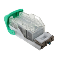
Parts information:
END FENCE:THREE
WAY:ASS'Y
Old end fence:
D1357561 [A]
Temporary
end fence #1 [B]